


VB Series Outdoor LS Manual 31
Temperature Controller Installation
• The controller should be out of reach of small
children.
• Avoid locations where the controller may become
hot (near the oven or radiant heater).
• Avoid locations in direct sunlight. The digital
display may be difficult to read in direct sunlight.
• Avoid locations where the temperature controller
could be splashed with liquids.
• Do not install in locations where it can be adjusted
by the public.
Configurations
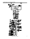
A maximum of 4 temperature controllers, including
wired and wireless, can be installed for a water heater
or bank of water heaters. Controllers can only be
wired in parallel. Controllers cannot be wired in
series.
The 4 temperature controllers can consist of multiple
MC-91’s or MC-502RC’s but only 1 BC-100V and only
1 MC-100V.
Any one of the 5 types of controllers can be installed
by itself and still operate the water heater. All
functions will be available with the exception that the
clock function on the BC-100V will only be available if
an MC-100V is also connected.
If 4 MC-91’s are installed, simultaneously press the
Priority and On/Off buttons on the fourth controller
until a beep sounds.
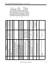
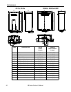
The table to the right shows some of the possible
combinations of controllers.
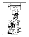
Cable Lengths and Size
The cable for the temperature controller should be a
non-polarized two-core cable with a minimum gauge
of 22 AWG. The maximum cable length from each
controller to the water heater depends on the total
number of wired controllers connected to the water
heater.
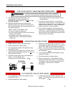
MC-91 + MC-91 + MCC-91 MC-502RC
MC-91 + MCC-91 + MC-502RC MC-502RC
MCC-91 + MC-502RC + BC-100V MC-100V
MC-91 + MC-502RC + BC-100V MC-100V
MC-91 + MC-91 + MC-502RC BC-100V
MC-91 + MC-502RC + MC-502RC MC-100V
+
+
+
+
+
+
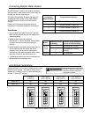
Number of Wired
Controllers
Maximum Cable Length for each
Controller to Water Heater
1 328 ft (100 m)
2 164 ft (50 m)
3 or 4 65 ft (20 m)
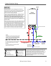
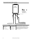
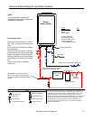
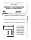
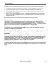
Location
Controllers
Wire controllers in parallel