


VB Series Outdoor LS Manual 23
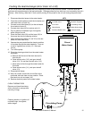
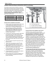
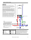
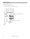
Pressure Relief Valve
3/4" Ball Valve
3/4" Union
Check Valve
S
Pressure Regulator
Circulating Pump
Solenoid Valve
Boiler Drain Valve
KEY
G
a
s
S
u
p
p
l
y
M
i
n
i
m
u
m
3
/
4
"
C
o
l
d
W
a
t
e
r
S
u
p
p
l
y
L
i
n
e
Minimum 3/4" Hot Water
Supply Line
S
1/2" Minimum
Normally Open
Solenoid Valve
3/4" Minimum
Normally Closed
Solenoid Valve
Route to Floor Drain
Vacuum
Breaker
NOTE:
ALL pipe and fittings shown below dashed line
should be located inside home or building
structure.
NOTE:
Heat trace ALL water pipe and fittings located
outside home (attic, crawl space) or building
structure. (ALL water pipe and fittings shown
above the dashed line in the drawing.)
Rinnai
Water Heater
3
/
4
"
G
a
s
C
o
n
n
e
c
t
i
o
n
S
The vacuum breaker line should be located
inside the building structure.
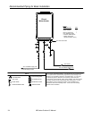
This is not an engineered drawing. It is intended only as a guide and not
as a replacement for professionally engineered project drawings. This
drawing is not intended to describe a complete system. It is up to the
contractor/engineer to determine the necessary components and
configuration of the particular system being installed. This drawing does
not imply compliance with local building code requirements. It is the
responsibility of the contractor/engineer to ensure installation is in
accordance with all local building codes. Confer with local building
officials before installation.
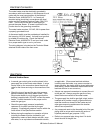
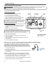
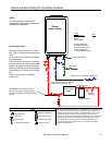
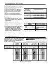
Freeze Protection Piping
Warranty does not cover damage due to freezing.
In the event of a power failure at temperatures below
freezing the water heater should be drained of all
water to prevent freezing damage.
The unit may be drained manually. However, Rinnai
highly recommends that drain down solenoid valves
be installed that will automatically drain the unit if
power is lost. Rinnai also recommends the installation
of a surge protector with terminals which allows the
solenoid valves to operate if the unit is disabled due to
an error code.
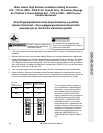
When the electrical power to the water heater fails, the
3/4” solenoid valve closes (stopping the flow of water
into the heater) and the 1/2” solenoid valve opens
(allowing the water heater and associated piping to
drain. Ensure that you run the drain for the solenoids
to the outside environment to prevent discharging
water inside the building causing water damage).
NOTICE