


VB Series Outdoor LS Manual 17
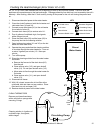
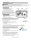
Clearances from Appliance
1. Identify the installation location and confirm that
the installation will meet all required clearances.
2. Securely attach the water heater to the wall using
any of the holes in the wall installation brackets
which are at the top and bottom of the water
heater. Ensure that the attachment strength is
sufficient to support the weight. Refer to the
weight of the water heater in the Specifications
section.
NOTE: Rinnai water heaters should be installed in an
upright position. Do not install upside down or on it
side.
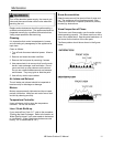
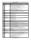
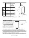
Attachment of the Water Heater
to Combustibles
to Non-
Combustibles
Top of
Heater
12 inches (305 mm) 2 inches (51 mm)
Back of
Heater
0 (zero) 0 (zero)
Front (Panel)
24 inches (610 mm) * 0 inches (0 mm)
Sides of
Heater
6 inches (152 mm) 1/8 inch (3.2 mm)
Ground/
Bottom
12 inches (305 mm) 2 inches (51 mm)
Front
(Exhaust)
24 inches (610 mm) 24 inches (610 mm)
* The clearance for servicing is 24 inches in front of
the water heater.
wall installation
brackets
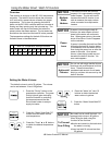
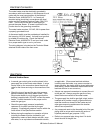
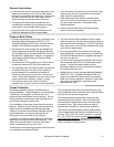
Error Indication or Air Handler Control Switch (RL75e and RL94e only)
When using the Rinnai water heater with an Error Indication Switch, dip switch No. 4 in the bank of 8 switches
should be in the off position. This is the default position.
To connect the water heater to the Rinnai Air Handler, the Control Switch is necessary to function as the electrical
connection. When the Control Switch is functioning as the electrical connection between the water heater and air
handler, dip switch No. 4 in the bank of 8 switches should be in the on position.
The Error Indication Switch and the Rinnai Air Handler Control Switch are optional products available from Rinnai.
Installation instructions are included with these products.
to side
to front
to top
to ground/bottom
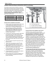
It is important not to block any of the air inlets which are located on the front and bottom panels of the case.