


Rinnai Corporation RHFE-750ETR 23
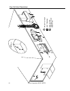
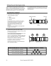
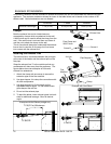
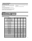
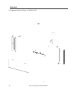
Extension Kit Installation
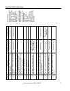
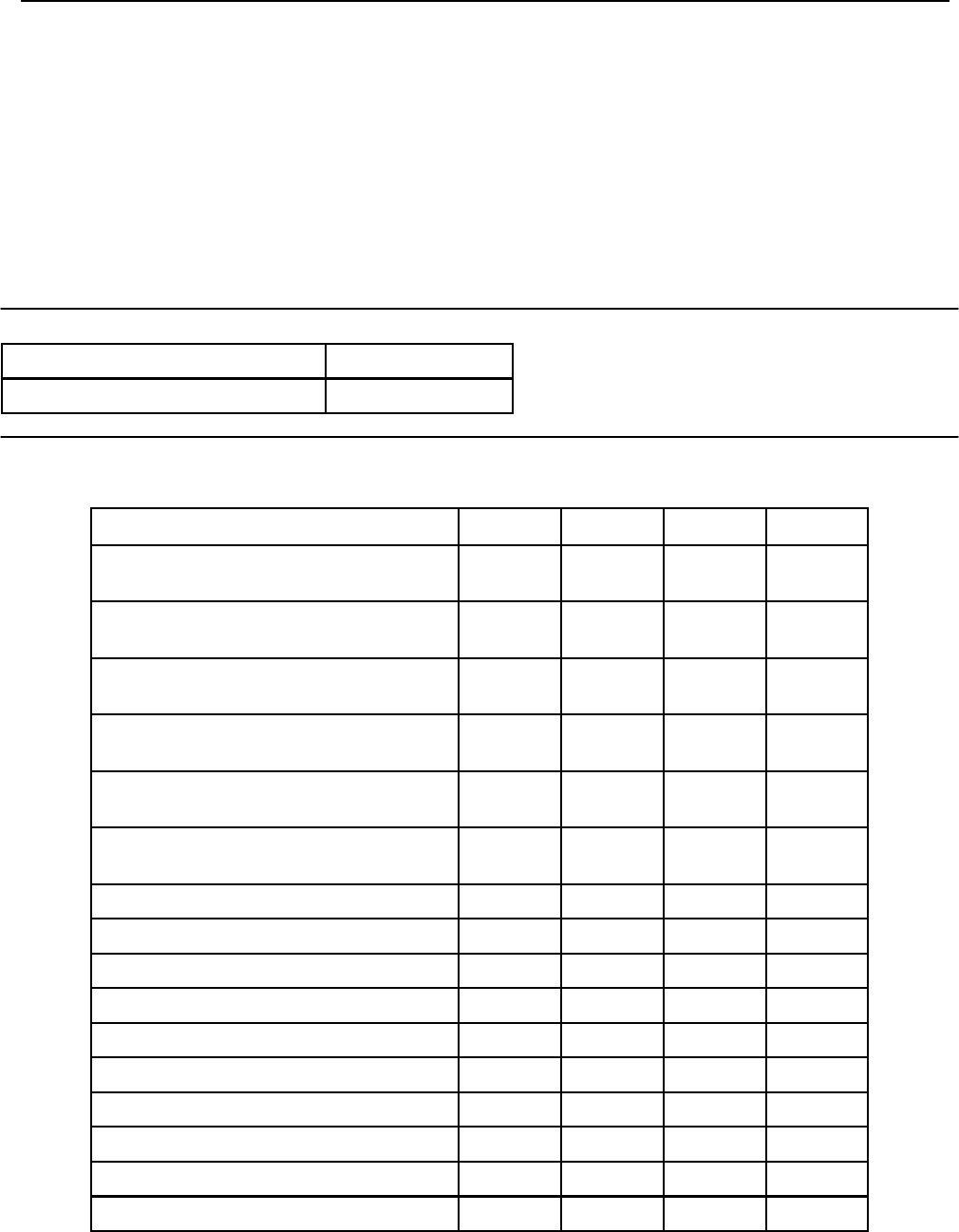
Description FOT-102 FOT-103 FOT-114 FOT-115
Exhaust Pipe (adjustable)
11.4-20.3 in (290-515 mm)
1
Exhaust Pipe (adjustable)
21.0-39.6 in (533-1005 mm)
1 1
Exhaust Pipe
40 in (1016 mm)
1
Air Intake Hose
29.5 in (750 mm)
1
Air Intake Hose
49.2 in (1.25 m)
1
Air Intake Hose
90.6 in (2.3 m)
1
Elbow (flexible) 1
Hose Joint 1 1 1
Pipe Stopper A 1 1 2 2
Pipe Stopper B 1 1 1
Top Stopper 1 1 1
Pipe Clamp 2 sets 3 sets 4 sets
Wall Fixture 2 3 4
Nut 2 3 4
Screw A 2 3 4
Screw B 4 6 8
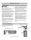
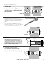
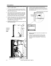
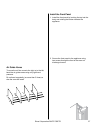
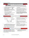
Connecting the Air Line
The air line is connected between the air connection
at the rear of the heater and the air intake port on the
flue manifold.
Push the air intake hose onto the flue manifold and
secure with the plastic cable tie.
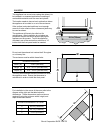
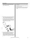
Join air intake hoses by screwing the hose joint half of
its length into the air intake hose and then screwing
another air intake hose into the hose joint.
The hose can be cut to the required length. Deburr all
rough edges.
Support the air line with pipe clamps.
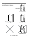
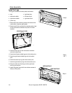
Clearances
exhaust pipe to combustibles 1 inch (25.4 mm)
exhaust pipe to non-combustibles zero
Extension Kits and Parts