


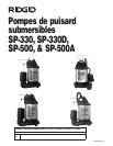
SP-330, SP-330D, SP-500, SP-500A Submersible Sump Pumps
Ridge Tool Company
Never cut off grounding prong or
use an adapter.
Support pump and piping when
assembling and after installation. Failure to do so
could cause piping to break or pump to fail, which
could result in property damage and/or personal injury.
5. Set pump into sump. Locate the pump on a solid
level surface.
Do not place directly on clay, gravel,
or any loose or sandy surfaces. These surfaces con-
tain small stones or sand that may clog or damage the
pump, which could result in pump failure causing
flooding and property damage.
6. This pump has a 1-1/2” NPT discharge. If existing
piping is 1-1/4” NPT, an adapter bushing (not
included) may be used. Do not use piping that is
less than 1-1/4” NPT. Piping that is too small will
result in reduced output.
7. A check valve is required in the discharge line to
prevent backflow when the pump shuts off. It is
best to install the check-valve directly to the pump
discharge. Thread a check valve into pump dis-
charge.
Be careful not to strip or cross-
thread. Do not use pipe joint sealant.
Flexible discharge hose is intended
for temporary use only. Rigid PVC or metal pipe is
required for a permanent installation. If flexible dis-
charge hose is temporarily used, make sure pump is
secured in sump pit to prevent movement. Failure to
secure pump could allow pump movement and cause
switch interference and prevent pump from starting or
stopping. This could result in flooding and property
damage.
IMPORTANT! Make sure there is adequate room for
float switch to move freely during operation. A 1”
minimum is required.
8. Connect 1-1/4” diameter rigid pipe to rubber boot
on check valve (not included). Reverse boot for 1-
1/2” diameter pipe. Tighten clamps.
NOTICE
NOTICE
NOTICE
!
WARNING
!
WARNING
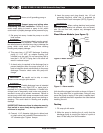
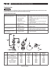
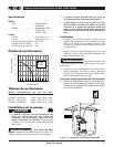
9. Insert the pump cord plug directly into 115 volt
grounded electrical outlet that is protected by
Ground Fault Circuit Interrupter (GFCI)
(Figure 1)
.
When routing electrical cord protect
cord from sharp objects, hot surfaces, oils, and chemi-
cals. Do not kink cord, replace any damaged cord
immediately.
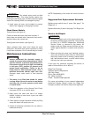
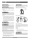
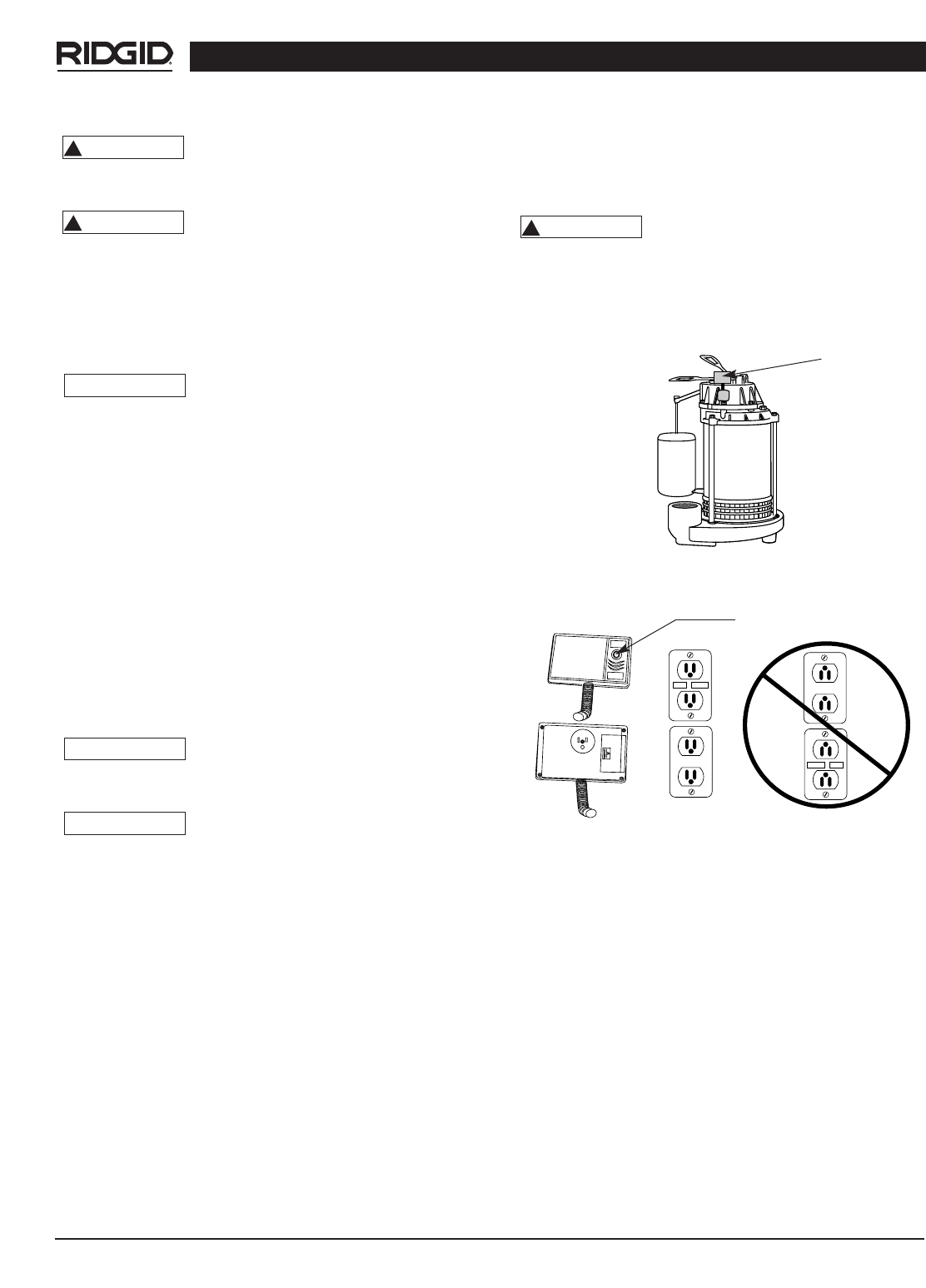
Flood Alarm Models (see figure 3)
Figure 3- Water Sensor
Figure 4 – Alarm models
Unit should be plugged into outlet as shown in figure 4.
Do not plug alarm box in upside down. Doing so may
cause the pump to unplug. If the outlet is upside down,
have a qualified electrician reposition the outlet before
installing the unit.
Testing
1. Fill sump pit with water.
2. While the pump is draining the pit, verify that the
discharge piping is carrying the water to a point at
least 15 feet away from the foundation.
!
WARNING
TEST
RESET
TEST
RESET
Test Button
Water
Level
Sensor
5