


The water heater must be installed with a 3”/5” diameter UL approved Category III Coaxial Stainless Steel
appliance coaxial vent pipe and an appropriate adapter.
Venting
The installation of venting must comply
with national codes, local codes and the
vent manufacturer’s instructions.
The water heater must be vented to the
outdoors as described in these instructions.
DO NOT connect this water heater to a
chimney. It must be vented separately from
all other appliances.
All coaxial vent components (adapters, pipe,
elbows, terminals, etc.) should be UL 1738
Certified Stainless Steel Venting Material
(e.g. AL29-4C).
The specified vent termination must be used.
(Refer to pages 13 and 14 for an example of
the concentric vent.)
Use the screws provided to connect the
coaxial vent pipe with the anti-disconnection
joint.
Follow coaxial vent manufacturer’s
installation instructions and their
recommended clearances to combustibles.
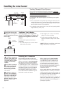
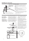
The unit can be vented either horizontally
or vertically.
Coaxial vent pipe runs must be adequately
supported along both horizontal and vertical
runs.
The maximum recommended unsupported
span should be no more than five (5) feet
(1.5 m). Support isolation hanging bands
should be used. DO NOT use wire. (See
diagram below).
Notes on pre-existing vent:
If the water heater is being installed as a
replacement for an existing water heater, a
thorough inspection of the existing venting
and air intake system must be performed
prior to any installation work. Verify that the
correct materials, vent lengths and terminal
locations as detailed in this Use and Care
Manual have been met. Carefully inspect the
entire venting and air intake system for any
signs of cracks or fractures, particularly at
the joints between elbows or other fittings
and the straight runs of vent pipe. Check the
system for signs of sagging or other stresses
in the joints as a result of misalignment of
any components in the system. If any of
these conditions are found, they must be
corrected in accordance with the venting
instructions in this manual before completing
the installation and putting the water heater
into service.
See the back page of this manual
for additional requirements for the
Commonwealth of Massachusetts.
DANGER: Failure to
install the appliance vent
adapter and properly vent
the water heater to the
outdoors as outlined in the
Venting section of this
manual will result in unsafe
operation of the water
heater, causing death,
serious injury, explosion,
or fire. To avoid the risk
of fire, explosion, or
asphyxiation from carbon
monoxide, NEVER operate
the water heater unless it is
properly vented and has
adequate air supply for
proper operation as
outlined in the Venting
section of this manual.
WARNING: Use 3”/5”
UL approved Category III
Stainless Steel vent
material only. No other
vent material is permitted.
WARNING: Refer to
page 7 for clearances to
combustible material.
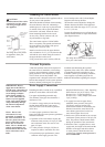
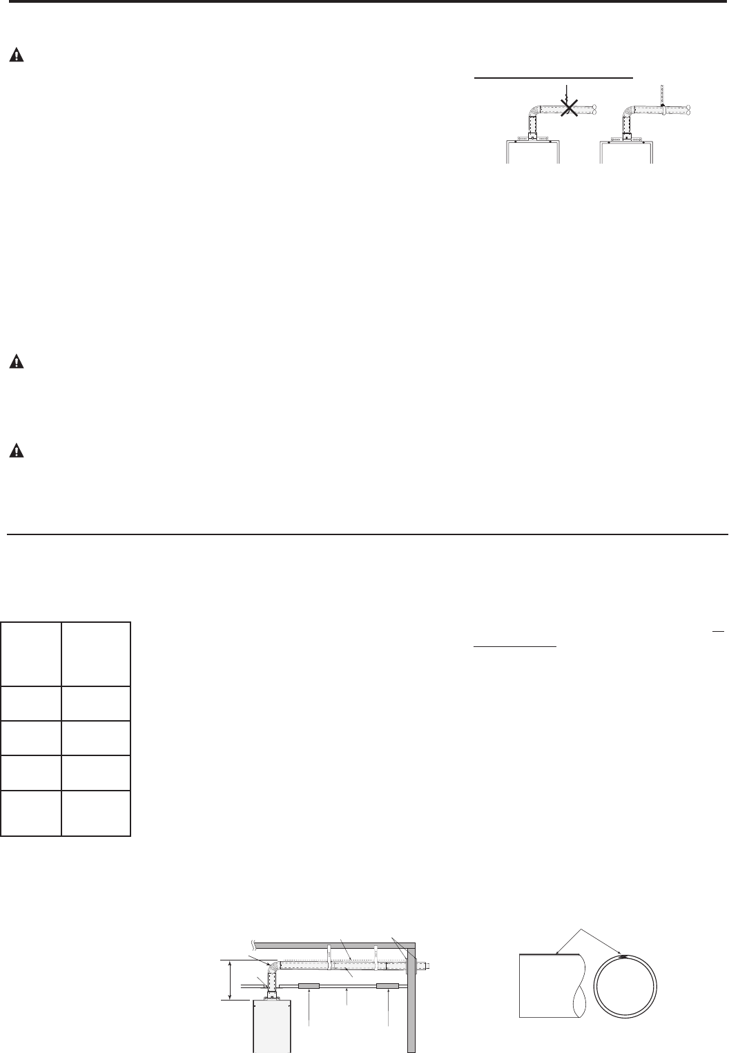
NO!
YES!
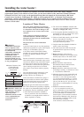
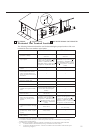
Venting Lengths
MAXIMUM VENT LENGTH: The
system will not operate if there is excessive
restriction (pressure drop) in the venting
system. A maximum 26’
(8.0 m)
of vent pipe
may be used provided there is only one 90°
elbow in the system. If additional elbows are
required: two elbows can be used with 24’
6"
(7.5 m)
, three elbows can be used with
23’
(7.0 m)
or four elbows can be used with 21
’
6"
(6.5 m) of vent pipe.
A 90° elbow is equivalent to 1’6” (.5 m) of
straight pipe. A 45° elbow is equivalent to
9” (.25 m) of straight pipe.
The vent termination does not count as
straight pipe when determining total vent
lengths.
The 94° elbow is equivalent to a 90° elbow.
The vent should be installed with a slight
downward slope of 7/8” per foot of
horizontal run toward the vent terminal (see
diagram below). This ensures that any
condensate formed during operation of the
unit is evacuated from the appliance and to
prevent rain from entering the appliance.
An upward slope toward the vent terminal is
not acceptable for horizontal venting.
MINIMUM VENT LENGTH: The venting
may be as short as 12” (30 cm), provided
one vent termination is installed to the
outdoors through a sidewall, one 94° elbow
is included in the installation and the wall
plates are installed.
Notice: Make sure that the seam of the inner
vent pipe in horizontal runs is toward the
top of the installation (see diagram to the far
left).
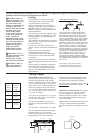
Vent Seam
Number
of 90°
elbows
(bends)
Maximum
Length of
Straight
Pipe
1 26’
(8.0 m)
2 24' 6"’
(7.5 m)
3 23"
(7.0 m)
4 21' 6"
(6.5 m)
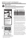
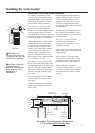
9
downward slope
7/8" per foot
Ceiling
Vent Pipe
Wall Plates
Board
Inspection
Fire
Stop
Access Panel #1
Inspection
Access
Panel #2
2’
(61 cm)
Max.
94° Elbow