


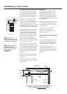
Electrical Connection
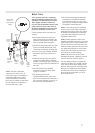
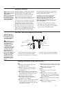
POWER CORD:
● The electric power supply requirement
for this water heater is 120 VAC/60HZ,
2 Amps.
● The water heater comes with a three (3) pin
power supply cord. Use only a power outlet
with a ground terminal.
● The installation of an GFCI (Ground Fault
Circuit Interrupter) is recommended.
● Keep any excess of the power supply cord
on the outside of the water heater.
● If local codes require hardwiring, see
instructions for “Hardwiring the Electrical
Connections”.
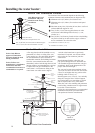
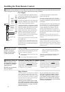
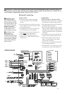
HARDWIRING
THE ELECTRICAL CONNECTIONS:
● Wiring should be carried out by a qualified
electrician in accordance with local codes.
● The water heater requires 120 VAC/60Hz and
should be properly grounded.
● DO NOT connect grounding wire to water
pipes, gas pipes, telephone cables, lightning
conductor circuits and to grounding circuit
of other equipment that carry a ground-fault
interrupter.
● An ON/OFF switch must be provided and
installed for the incoming 120VAC power.
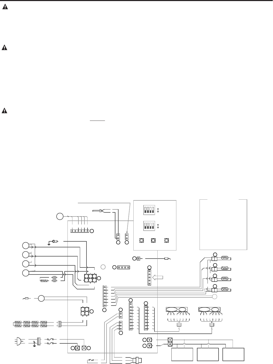
● Wire the water heater exactly as shown
below. A wiring diagram is also found
inside of the cover panel.
● A green screw is provided in the enclosure
for a grounding connection.
● Connect the live wire to black leg wire and
the neutral wire to the white neutral wire.
WARNING: Shock
hazard line voltage is
present. Before servicing
the water heater, turn off
the electrical power to the
water heater at the main
disconnect or circuit
breaker. Failure to do so
could result in severe
personal injury or death.
CAUTION: Label
all wires prior to
disconnection when
servicing controls. Wiring
errors can cause improper
and dangerous operation.
Verify correct operation
after servicing.
WARNING: Field wiring connections and electrical grounding must comply with local codes, or
in the absence of local codes, with the latest edition of the National Electrical Code, ANSI/NFPA 70,
or in Canada, Canadian Electrical Code, CSA C22.1 Part 1.
21
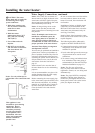
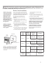
BK
CONTROL
BATH
BATH
CONTROL1
CONTROL2
BK:BLACK
BR:BROWN
R:RED
W:WHITE
GY:GRAY
O:ORANGE
Y:YELLOW
G/Y:GREEN/YELLOW
REMOTE
REMOTE
REMOTE
(UMC-117)
(USC1-117)
(USC2-117)
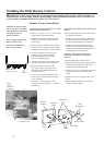
WIRING DIAGRAM
CIRCUIT
BOARD
U
2
1
S
1
3
2
W
W
OFF
ON
1
2
3
4
I
J
H
F
D
E
MOTOR
R Y O
W
BR
SW2
SW1
SW3
MAIN
W
W
1
2
Q P
OFF
ON
2
3
4
1
MAX
BUTTON
ADJUSTER
BUTTON
MIN
BUTTON
DIP
SWITCH2
DIP
SWITCH1
31-92028 0
8
B
R
Y
O
W
BR
BK
1
2
3
4
5
6
7
8
R
Y
O
W
BR
BK
1
2
3
4
5
6
7
8
C
9
BK
MOTOR
R Y O
W
BR
8
R
BR
BK
BK
W
GND
BK
W
1
2
3
4
Y
W
BK
R
1
23
456
K
SV0
SV1
SV2
SV3
BK
BK
BK
W
BK
W
BK
G/Y
GY
BK
IG
R
W
1
2
1
23456
G
FM
5
GY
W
Y
R
R
BK
BK
R
1
2
3
4
5
6
7
+
PSV
R1
R2
R3
R4
BK
BK
-
BK
W
M
( )
WW
COLOR CODE
Y
W
R
BK
AMBIENT
AIR
THERMISTOR
WATER
INLET
THERMISTOR
HEAT
EXCHANGER
THERMISTOR
OUTLET
HOT WATER
THERMISTOR
CONTROL MOTOR
WATER VOLUME
WATER BY-PASS
CONTROL MOTOR
PROGRAM
CHIP
FLAME ROD1
CONNECTOR FOR CHECKING
THERMOELECTROMOTIVE FORCE
FA N
MOTOR
THERMOCOUPLE
SOLENOID
VALVE 3
SOLENOID
VALVE 2
SOLENOID
VALVE 1
GAS INLET
SOLENOID
VALVE 0
GND
RESISTOR
ELECTRODE
IGNITER
ANTI-FROST
HEATER
AC
120V
FUSE(3A)
OVER HEAT
LIMITER
WATER
FLOW
SENSOR
P.G.F.R
VALVE
LED
LIMITER LIMITER
BL:BLUE
G:GREEN
BL
BL
G/YorG
W
BK
BL
BL BL
G G
BL
BL
GG BL BL
USUALLY
DISCONNECTED
1
2
3
4
5
A
4 3 2
1