


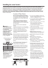
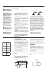
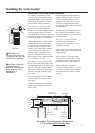
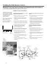
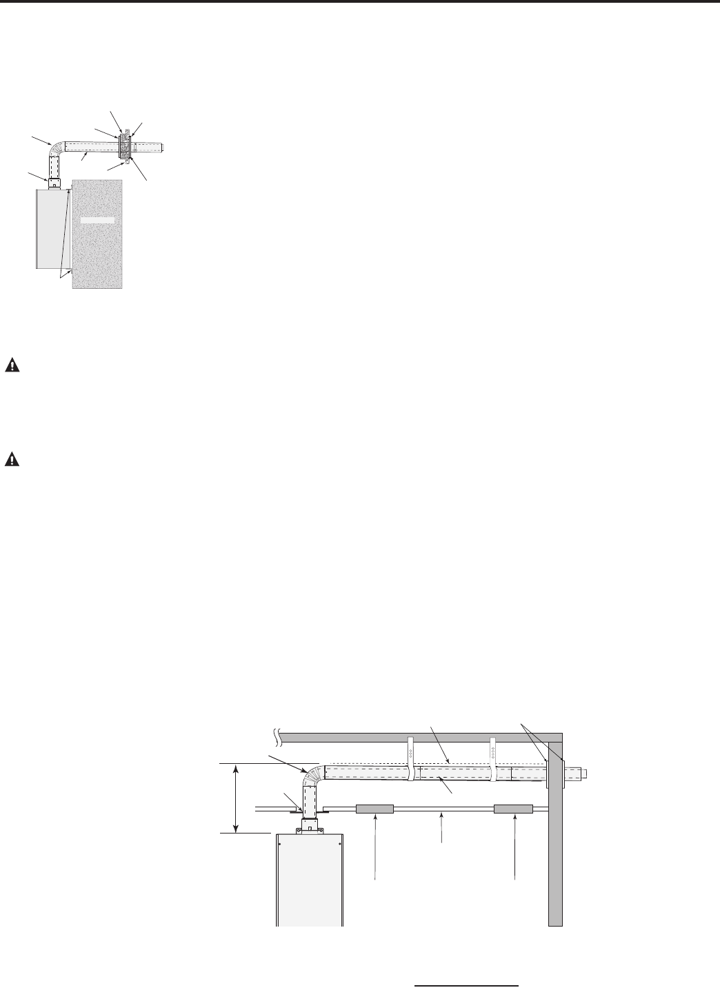
Example A: Typical Horizontal Termination
w/ 7/8” per foot DOWNWARD Slope
13
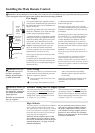
Installing the water heater:
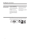
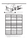
94° Elbow
Outer
W a ll
Inner Wall Plate
W a ter
Heater
Outside Wall
Side View
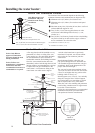
Caulk for
weather seal
Inner Wall
Outer Wall Plate
Vent
Pipe
Mounting
Brackets
Appliance
Vent Adapter
Side View
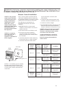
WARNING: Use
UL approved Category III
vent material only. No other
vent material is permitted.
CAUTION: Follow the
vent manufacturer’s
installation instructions as
design might vary from
manufacturer to
manufacturer.
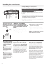
Horizontal Vent Installation continued.
Use 4 hollow wall anchors, at least
1/8 inch (0.32 cm) in diameter and of
appropriate length for the thickness of
the sheathing, if sheathing is particle
board or other composite material.
Use 4 #10x1-1/4” wood screws for
plywood, solid wood sheathing or
members. Use suitable masonry anchors
when passing through solid masonry
walls. Reinstall the decorative sheathing
around the faceplate. This assembly may
be painted to match the exterior decor.
Apply silicone sealant or silicone/latex
caulk around the vent section where
it passes through the plate and around
the plate where it is attached to the
structure. This will provide a weather
seal to keep moisture outside the
building. Ensure a sufficient seal is
made. Now attach the female end of
the air intake tee to the male end of the
3”/5” concentric vent pipe.
Push firmly on the air intake tee until
the outer jacket has made contact with
the snap ring located on the male end of
the 3”/5” concentric vent pipe section.
When fully assembled the outer female
end will overlap the male end 1 inch
(25.4 mm).
Use the self-tapping screws provided
with the vent kit to connect the two
outer pipes.
Seal the over lapping area of the outer
pipe (5” concentric pipe) with a thick
bead of caulk.
Install the appliance adapter onto the
appliance and use (4) four screws to
secure the appliance adapter to the
appliance. Now attach other required
vent and air intake material between
the appliance adapter and the horizontal
vent termination.
Maintain the proper clearance between
the vent pipe and combustible or non-
combustible material as required by the
vent manufacturer.
There is a 1" (2.5 cm) minimum
clearance required between air
intake pipe and combustible or non
combustible material.
Proper support be provided for the vent
and air intake pipes as mentioned in the
venting section.
Support method used should isolate
the vent pipe from floor joist or other
structural members to help prevent the
transmission of noise and vibration.
Do not support, pin, or otherwise
secure the venting system in a way that
restricts the normal thermal expansion
and contraction of the chosen venting
material.
downward slope
7/8" per foot
Ceiling
Vent Pipe
Wall Plates
Board
Inspection
Fire
Stop
Access Panel #1
Inspection
Access
Panel #2
2’
(61 cm)
Max.
94° Elbow