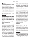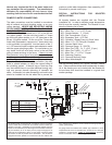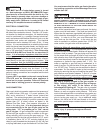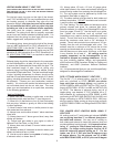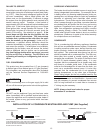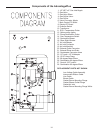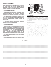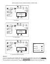
VENTING WHEN USING 3" VENT PIPE
(ONLY MODELS WITH INPUTS OF 100,000 BTU AND 130,000 BTU
ARE CERTIFIED TO USE 2" VENT PIPE, SEE SPECIAL VENTING
INSTRUCTIONS SECTION)
For inlet air supply, top pipe on the right of the shroud,
use 3" PVC schedule 40. It is very important that you plan
the location properly to eliminate long pipe runs and
excessive fittings. Inlet pipe size must not be reduced.
Do not combine the inlet air with any other inlet pipe
including an inlet to an additional similar appliance.
The joints must be properly cleaned, primed, and
cemented. The piping must also be properly supported
as per local and national standard plumbing codes. It is
important that the piping be clean and free from burs,
debris, ragged ends, and particles of PVC.
For exhaust piping, lower pipe on the right of the shroud,
use only ABS schedule 40 or CPVC schedule 40 or 80,
NON FOAM CORE
, in the first 84" (7 feet) of vent length.
The balance of the inlet and exhaust piping may be PVC
schedule 40, ABS schedule 40 or CPVC schedule 40 or
80, NON FOAM CORE ONL
Y, as required to meet local
venting codes.
Exhaust piping should be sloped back to the connection
on the AdvantagePlus, at least 1/4 inch per foot of pipe,
to remove the condensate that forms within the pipe. The
total combined length of pipe, (inlet air piping plus
exhaust piping) including allowances for elbows, should
not exceed 85 equivalent feet. The total combined length
of pipe, including allowances for elbows, should not be
less than 22 equivalent feet (minimum length of 12 feet of
piping, including allowances for elbows, on the inlet and
the exhaust). Choose your vent termination locations
carefully. You must make certain that exhaust gas does
not re-circulate back into the air inlet pipe. You must
place your vent terminations in an open area, according
to the following guidelines.
V
enting Guidelines
1) Never vent into a walkway or patio area, or an alley,
or otherwise public area less than 7' from the ground.
2) Allow four (4) feet below or four (4) feet horizontally
from any door, window or gravity air inlet to the building
or other appliance.
3) Never install a heat saver or similar product to cap-
ture waste heat from exhaust.
4) Always have vent location at least 1' above maximum
snow level.
5) Always have vent 1' above ground level, away from
shrubs and bushes.
6) Follow local gas codes in your region or refer to
National Fuel Gas Code, or Can B149.
7) Always have vent at least 3' from an inside corner of
outside walls.
8) Maintain at least 4' clearance to electric meters, gas
meters and exhaust fans or inlets.
9) Inlet air must be taken from outside of building next
to exhaust outlet, no closer than 8".
10) Always place 1/2 inch x 1/2 inch 16 gauge galva-
nized steel screen in the intake and exhaust openings to
prevent foreign matter from entering the AdvantagePlus.
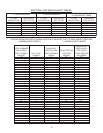
11) The vent system must be balanced by friction loss
equivalent (See table on page 10).
12) The same method must be used for both intake and
exhaust termination. DO
NOT terminate one horizontal-
ly and the other vertically.
13) Roof Venting: The vent intake and exhaust must be
properly cleaned and glued, for pressure tight joints.
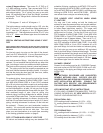
Several methods for venting the AdvantagePlus can be
found on pages 22 and 23. Use the layout as a guide-
line. Certain site conditions such as multiple roof
lines/pitches may require venting modifications-consult
factory. The air inlet must be a minimum of 1' vertically
above the maximum snow level or 24" whichever is
greater. The air inlet must also be a minimum of 10' hor-
izontally from the roof and terminated with a tee. The
exhaust must be a minimum of 24" above the air inlet
opening and terminated with a coupling. It is very impor-
tant that there are no other vents, chimneys, or air inlets
in any direction for at least 4'. All venting must be
properly supported, as the AdvantagePlus is not
intended to support any venting whatsoever. All pip-
ing, glue, solvents, cleaners, fittings, and components
must conform to ASTM (American Society for Testing and
Materials), and ANSI (American National Standard
Institute).
14) It is recommended that you use vent kits specifically
designed for AdvantagePlus installations.
PIPE / FITTINGS WHEN USING 3” VENT PIPE
The first 84" (7’) of exhaust piping, must be of 3" ABS
solid only (provided) or CPVC; (NEVER use cellular
foam core pipe on exhaust piping), and conform to
ASTM D-3965 for ABS or ASTM F-441 for CPVC, and fit-
tings to ASTM D2661 & D3311 for ABS and ASTM F-439
for CPVC. The balance of exhaust piping, and all of
intake piping, use standard 3" PVC schedule 40 or 3"
ABS schedule 40, conforming to ASTM D2665, or ABS
conforming to ASTM D-3965 & ASTM R-441 for ABS; and
fittings conforming to ASTM D-2665 & D331. ABS may
also be used for intake venting as long as pipe conforms
to ASTM D3965 & D2661 and fittings meet ASTM D2661
& D3311.
FOR LONGER VENT LENGTHS WHEN USING 3”
VENT PIPE
All venting must be 3", both intake and exhaust. NEVER
use any piping less than 3", or different size pipe on
the intake and exhaust. You may use 4" venting on
both intake and exhaust to lower the pressure drop and
provide additional venting length. It is imperative when
using 4" venting to follow these instructions very
carefully. For longer venting lengths, the first 10' of
both the intake and exhaust piping are 3". For the
intake, use 10' of 3" PVC plus one 90 degree or two
45 degree elbows. For the exhaust, use 10' of ABS
solid NON FOAM CORE, or CPVC plus one 90 degree
8


