26
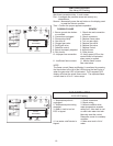
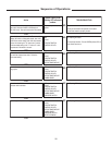
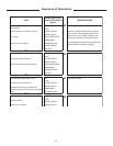
Sequence of Operations
Fill tank
Ensure gas connections are present and no leaks
Ensure water heater is properly vented
YES
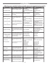
LINE See Flashing LED table
24 VAC
ECO/VENT SWITCH
CONTROL HEALTH
YES
LINE See Flashing LED table
24 VAC
ECO/VENT SWITCH
CONTROL HEALTH
WATER TEMPERATURE
YES
LINE See Flashing LED table
24 VAC
ECO/VENT SWITCH
CONTROL HEALTH
WATER TEMPERATURE
COMB BLOWER
YES
LINE See Flashing LED table
24 VAC
ECO/VENT SWITCH
CONTROL HEALTH
WATER TEMPERATURE
COMB BLOWER
PRESSURE SWITCH
YES
LINE See Flashing LED table
24 VAC
ECO/VENT SWITCH
CONTROL HEALTH
WATER TEMPERATURE
COMB BLOWER
PRESSURE SWITCH
IGNITER ELEMEN
T
YES
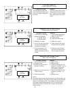
Tank is cold, full of water, gas supply is connected to
gas control valve and heater is connected to a
120 VAC circuit. Gas valve is set to the ON position.
None. No power has been
applied.
System Lights (LEDs)
Flashing LED indicates a
problem
Action
Thermostat calls for heat. Water temperature inside
the tank has dropped more than 4˚ below the
thermostat setting.
Combustion blower is powered for a 40 second pre-
purge cycle.
Once there is sufficient combustion airflow, the
pressure switch activates.
Turn electric to main power to ON. The control will
display "00" which is a diagnostic check; then "120"
which is the control voltage; then "08" which means
plus or minus setting is 8˚ (4˚ above and 4˚ below)
from thermostat setting; then "??" where ?? is the
temperature of the water in the tank.
Igniter begins 30 second warm up period.
NO
NO
NO
NO
NO
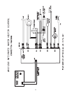
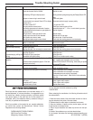
TROUBLESHOOTING
NO
Unit is polarity sensitive. Ensure GREEN polarity LED on
main control board is on.


