


13
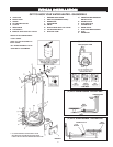
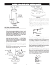
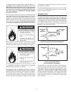
FIGURE 15.
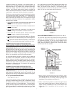
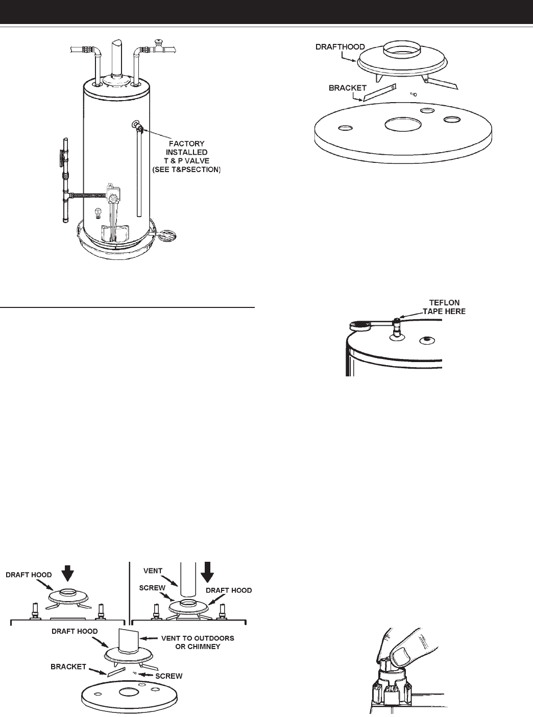
SECTION A - GALVANIZED PIPING
(See Figure 15)
1. Position the water heater so that the existing piping will
require the shortest distance between connections. Make
sure that you are able to reach the drain valve and all
connections when the water heater is in place. This will
make it easy to service the water heater. The water heater
must be level before you begin the piping.
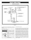
If a water heater is installed in a closed water supply system,
such as one having a back-flow preventer, check valve,
water meter with check valve, etc. . . in the cold water
supply, means shall be provided to control thermal
expansion. Contact a qualified installer or service agency
on how to control this situation.
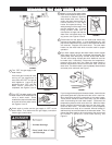
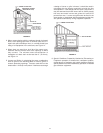
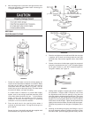
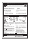
2. Place the draft hood in the receiving holes where it
connects to the water heater. The legs should snap in to
give a tight fit.
Secure the legs of the draft hood with the supplied draft
hood brackets, see Figures 16 and 16A.
FIGURE 16.
FIGURE 16A.
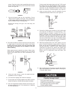
3. Place the vent pipe over the draft hood. With the vent pipe
in position, drill a small hole through both the vent pipe
and draft hood. Secure them together with a sheet metal
screw.
4. Wrap the 1” NPT threaded nipples (75 gallon models) or
1.25” NPT threaded nipples (100 gallon models) with teflon
tape or pipe joint compound, see Figure 17. Connect the
existing piping to the water heater.
FIGURE 17.
5. See the Temperature-Pressure Relief Valve section for
instructions on installing the discharge pipe.
6. Connect the flexible gas connector to the incoming gas
line using the end with the 1/2” female fitting, a 1/2”
threaded nipple is available if needed. The 1/2” male fitting
on the other end is to be connected to the gas thermostat.
Make sure that the gas type you have is the same as the
gas type indicated on the rating plate. Make sure that all
connections are tight. All threaded fittings must have teflon
tape or pipe dope (which is resistant to the action of liquefied
petroleum (L.P. Gas) applied, see Figure 15.
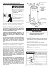
7. With the thermostat knob in the “OFF” position, turn the
gas on. Check for leaks with a soapy solution. If leaks are
found, turn the gas off immediately and correct. Do not
test for gas leaks with a match or flame. Read Lighting
instructions on page 20 for natural gas models and page
21 for propane gas models. Do not light the water heater
until it is completely filled with water.
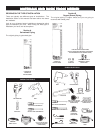
FIGURE 18.
INSTINST
INSTINST
INST
ALLING THE NEW WALLING THE NEW W
ALLING THE NEW WALLING THE NEW W
ALLING THE NEW W
AA
AA
A
TER HEATER HEA
TER HEATER HEA
TER HEA
TERTER
TERTER
TER