


12″ min.
FORCED AIR
INLET
A
36″ min. IF “B” DIMENSION
IS LESS THAN 120″
A
PDV
TERMINAL
PDV
TERMINAL
A
GRADE
“B”
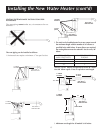
CORNER INSTALLATION
OF INLET AND OUTLET
NOT RECOMMENDED
8
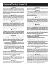
Locating the New Water Heater (cont’d)
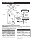
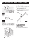
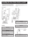
Figure 2
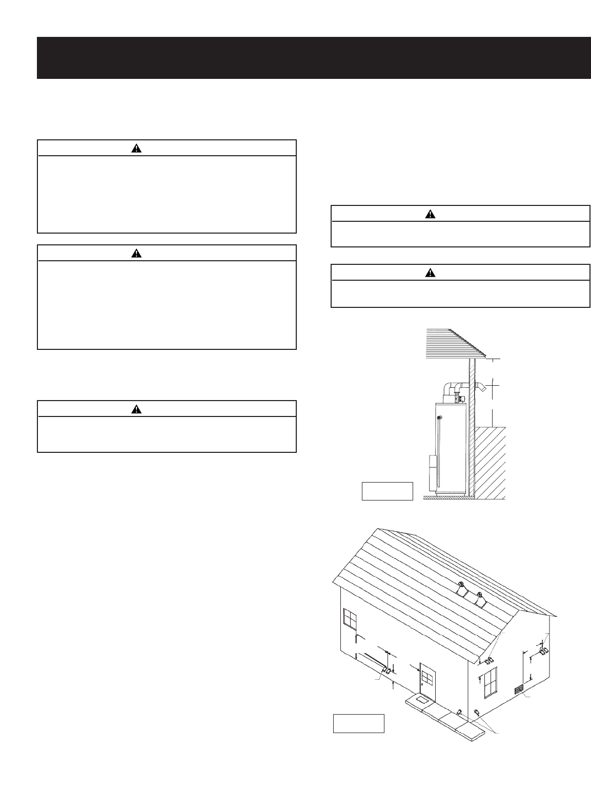
Combustion Air and Exhaust
Venting Through an Outside Wall – Clearances
•
0″ clearance for 3″ PVC, ABS, or CPVC Schedule 40 piping from
combustible surfaces.
•
18″ minimum in all directions from any obstruction, such as a wall,
that may interfere.
•
12″ minimum from the ground and corners, 9″ ceiling overhangs.
Figure 2.
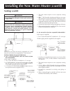
•
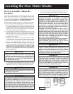
The Power Direct Vent outlet terminal shall terminate at least 36″
above any forced air inlet located within 10 feet. Figure 3.
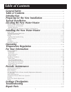
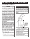
•
The Power Direct Vent outlet terminal of 50,000 BtuH input mod-
els or less shall terminate at least 9″ below, 9″ horizontally from or
9″ above any door, window or gravity air inlet into the building.
Figure 3.
•
The Power Direct Vent outlet terminal of over 50,000 BtuH input
models shall terminate at least 12″ below, 12″ horizontally from or
12″ above any door, window or gravity air inlet into the building.
Figure 3.
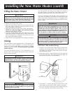
•
18″ minimum from other natural draft (gravity) direct vent, power
vent or power direct vent appliance inlet and/or outlet vent(s) when
directly above or 135° to either side of center line. Figure 4, page 9.
•
24″ minimum from any appliance inlet and/or outlet vents when
directly below or 45° to either side of center line. Figure 4, page 9.
•
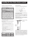
The location selection must provide clearances for servicing and
proper operation of the water heater. Figure 5.
•
Vent termination must not be within 4 feet of any items such as gas
meters, gas valves or other gas regulating equipment.
Facts to Consider About the
Location (cont’d)
Figure 3
WARNING
Failure to have required clearances between water heater
and combustible material will result in a fire hazard.
WARNING
Vent termination must not be within 4 feet of any items such as
gas meters, gas valves or other gas regulating equipment.
WARNING
When determining the installation location for a power direct
vent water heater, snow accumulation and drifting should be
considered in areas where applicable.
WARNING
If this water heater will be used in beauty shops, barber shops,
cleaning establishments, or self-service laundries with dry clean-
ing equipment, it is imperative that the water heater or water
heaters be installed so that combustion and ventilation air be
taken from outside these areas. Refer to the “Locating The New
Water Heater” section of this manual and also the current edi-
tion of the National Fuel Gas Code, ANSI Z223.1, also referred
to as NFPA 54 for specifics provided concerning air required.
WARNING
Do not install in a confined area such a closet, unless you
provide ventilation air as shown in the “Locating The New
Water Heater” section. Never obstruct the flow of ventila-
tion air. If you have any doubts or questions at all, call your
gas company. Failure to provide ventilation air can result in a
fire or explosion and can cause DEATH, SERIOUS BODILY
INJURY, OR PROPERTY DAMAGE.
C
Lof Flue
9″ min. from
any overhang
12″ min.
A
A - 9″ min. (50,000 BtuH
input models or less)
A - 12″ min. (over 50,000
BtuH input models)
•
The venting system must be installed in a manner which allows
inspection of the installation of the venting pipes and joints as
well as periodic inspection after installation as required by the
National Fuel Gas Code ANSI Z223.1.