


Installing the New Water Heater (cont’d)
A gas line of sufficient size must be run to the water heater.
Consult the current edition of National Fuel Gas Code ANSI
Z223.1, also referred to as NFPA 54 and the gas company
concerning pipe size.
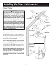
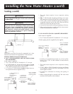
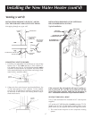
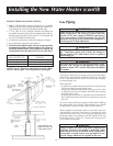
There must be:
—A readily accessible manual shut off valve in the gas sup-
ply line serving the water heater, and
—A drip leg (sediment trap) ahead of the gas control valve
to help prevent dirt and foreign materials from entering
the gas control valve.
—A flexible gas connector or a ground joint union between
the shutoff valve and control valve to permit servicing of
the unit.
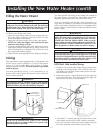
Be sure to check all the gas piping for leaks before lighting
the water heater. Use a soapy water solution, not a match
or open flame. Rinse off soapy solution and wipe dry.
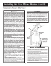
When installed at elevations above 2,000 feet, input rat-
ings should be reduced at the rate of 4 percent for each
1,000 feet above sea level which requires replacement of
the burner orifice in accordance with the National Fuel Gas
Code ANSI Z223.1 / NFPA 54. Contact your local gas util-
ity for further information.
Gas Piping
WARNING
Make sure the gas supplied is the same type listed on the
model rating plate. The inlet gas pressure must not
exceed 10.5 in. water column (2.6kPa)for natural gas or
13 in. water column (3.2 kPa) for propane (L.P.) gas. The
minimum inlet gas pressure listed on the rating plate is
for the purpose of input adjustment.
WARNING
If the gas control valve is subjected to pressure exceed-
ing
1
/
2
pound per square inch (3.5kPa), the damage to
the gas control valve could result in a fire or explosion
from leaking gas.
WARNING
If the main gas line shutoff serving all gas appliances is used,
also turn “OFF” the gas at each appliance. Leave all gas
appliances turned “OFF” until the water heater installation
is complete.
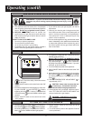
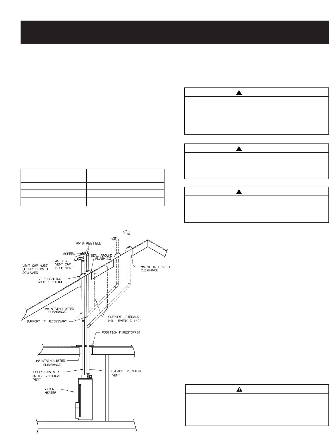
VENTING THROUGH A ROOF (CONT’D)
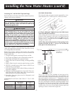
2. Only 3″ ABS Schedule 40 piping and fittings are acceptable
materials on the first five feet of the outlet vent system of 75
Gal. Models and 50 Gal. 65,000 Btu/Hr Models only.
3. 3″ PVC, ABS, or CPVC Schedule 40 piping and fittings are
acceptable materials for the inlet vent system and for the out-
let vent system (after the first five feet for 75 Gal. Models and
50 Gal. 65,000 Btu/Hr Models only).
4. It cannot be connected to existing vent piping or chimney.
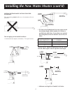
5. It must terminate vertically to the outdoors.
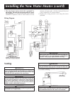
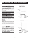
6. The total vertical and horizontal vent runs cannot exceed the
maximum length with a maximum number of 90˚ elbows as
specified in the table below. If more elbows are required, the
venting distance must be reduced 5 feet for every 90° elbow.
18
3″ DIA. VENTS NUMBER OF 90˚ DEG.
MAX. LENGTH (FT.) ELBOWS*
45 1
40 2
35 3
*NOTE: Two 45˚ elbows are equivalent to one 90˚ elbow.
One 90˚ elbow equals 5 feet of equivalent vent length.
TOTAL VERTICAL AND
HORIZONTAL RUNS - SEE
CHART ABOVE (ITEM 6).
WARNING
Failure to replace the orifice could result in improper and
inefficient operation of the appliance, producing carbon
monoxide gas in excess of safe limits, which could result in
serious injury or death. Contact your gas supplier for any
specific changes which may be required in your area.