


Regency F38-2 Freestanding Gas Heater
7
INSTALLATION
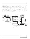
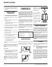
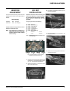
Flueing Requirements
A100 mm diameter fl ue is required. For cosmetic
or aesthetic purposes 6" outer fl ue can be used
as long as an approved inner fl ue is installed.
Fasten but do not penetrate the inner sleeve of
the fl ue when tightening the screw.
The minimum fl ue required is 3.3m from fl oor
level.
Follow all fl ueing manufacturer’s requirements
and local building codes or AS5601-2004.
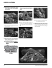
GAS CONNECTION
The gas line should be rigid pipe. Copper may
also be used if approved by AS5601-2004.
The gas connection at the valve is 1/2 male.
For minimum and maximum supply pressure
see the System Data Table.
GAS PIPE PRESSURE
TESTING
The appliance must be isolated from the gas
supply piping system by closing its individual
manual shut-off valve during any pressure
testing of the gas supply piping system at test
pressures equal to or less than 1/2 psig. (3.45
kPa). Disconnect piping from valve at pressures
over 3.45 kPa (14" w.c.).
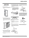
The manifold pressure is controlled by a regulator
built into the gas control, and should be checked
at the pressure test point.
Note: To properly check gas pressure,
both inlet and manifold pressures
should be checked using the valve
pressure ports on the valve.
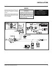
1) Make sure the valve is in the "OFF" posi-
tion.
2) Loosen the "IN" (# 7) and/or "OUT" (# 6)
pressure tap(s), turning counterclockwise
with a 1/8" wide fl at screwdriver.
3) Attach manometer to "IN" and/or "OUT"
pressure tap(s) using a 5/16" ID hose.
4) Light the pilot and turn the valve to "ON"
position.
5) The pressure check should be carried out
with the unit burning and the setting should
be within the limits specifi ed on the safety
label.
6) When fi nished reading manometer, turn
off the gas valve, disconnect the hose and
tighten the screw (clockwise) with a 1/8" fl at
screwdriver. Screw should be snug, but do
not over tighten.
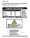
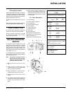
S.I.T. Valve Description
1) Gas on/off knob
2) Manual high/low adjustment
3) Pilot Adjustment
4) Thermocouple Connection
5) Main Operator
6) Outlet Pressure Tap
7) Inlet Pressure Tap
8) Pilot Outlet
9) Main Gas Outlet
10) Flange Securing Screw Holes
11) Alternative TC Connection Point
12) Thermoelectric Unit
13) Additional Valve Mounting Hole
F38-NG2: For 0 to 610 meters altitude
F38-LPG2: For 0 to 610 meters altitude
Burner Inlet Orifi ce Sizes:
NG LPG
Burner #33 #52
Max. Input
NG 38 mj
LPG 31 mj
Min. Input
NG 24.1 mj
LPG 24.5 mj
Supply Pressure
NG 1.74 kPa
LPG 2.99 kPa
Manifold Pressure
NG 0.87 kPa
LPG 2.65 kPa
Electrical: 240 V. 50Hz.
Circulation: High/Off/LO speed fan, 150/89
CFM.
Log Set: Ceramic fi ber, 7 per set.
Aeration Setting
NG Full Open
LPG 6.4 mm
Flue Restrictor Setting
NG Full Open
LPG Full Open
System Data
F38-2