


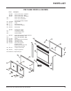
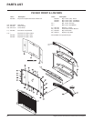
Regency P42-3 Zero Clearance Direct Vent Gas Fireplace 35
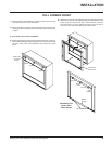
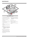
REMOVING VALVE
1) Shut off the gas supply.
2) Remove the louvers (and bay door if it is on).
3) Disconnect the inlet gas line.
Note: Be sure to have an 11/16" wrench
on the tee to ensure that the whole
line is not twisted
4) Disconnect the 2 TP wires and the 2 TH
wires from the valve.
5) Remove the Piezo igniter wire.
6) Open and remove the flush door.
7) Remove the logs.
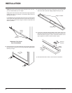
8) Remove the burner tube by removing the 3
Phillips head screws and then lift the burner
out.
9) Remove the burner grate assembly by re-
moving the 3 Phillips head screws on the
feet of the grate assembly.
10)Brush away all the vermiculite and embers
from the right hand half of the fireplace.
11)Remove the top and right hand side brick
panels.
12)Remove the 12 Phillips head screws secur-
ing the valve access plate in place and then
lift the entire assembly out.
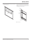
13)Undo the pilot tube from the valve with a
7/16" wrench.
14)Undo the quick drop out thermocouple nut
on the valve with a 9mm wrench.
15)Undo the "gas out" flare nut with a 13/16"
wrench.
16)
Undo the "gas out" 90
o
elbow flare fitting
with an 11/16" wrench.
17)Remove the 4 Phillips head screws from the
sides of the valve bracket and remove
valve.
Hint: If you are using black pipe, ensure
that there is a union by the valve, otherwise
removal will be almost impossible.
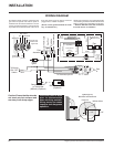
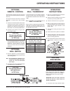
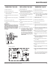
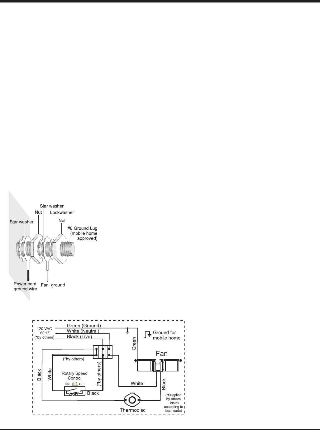
Grounding lug detail
REMOVING THE FAN
1) Shut the power off.
2) Remove the bottom louver.
3) Remove terminal block cover and discon-
nect the fan wires.
4) Disconnect white fan wire from the terminal
block.
5) Disconnect black fan wire from the thermo-
disc.
6) Disconnect fan ground wire.
7) Lift the fan off the two mounting studs and
pull out.
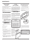
IMPORTANT:
These fans collect a lot of dust from
within your home. Ensure you main-
tain these fan motors on a regular
basis by vacuuming out the fan squir-
rel cages.
REPLACING THE FAN
1) Shut the power off.
2) Remove the bottom louver. Slide the fan in
and push it towards the rear of the unit and
slip it over the two mounting studs.
3) Remove the terminal block cover. Wire the
fan to the terminal block as shown in the
wiring diagram below.
4) Connect white wire from fan to neutral of
terminal block.
5) Connect black wire from fan to the thermo-
disc.
6) Connect fan ground wire. Refer to wiring
diagram.
7) Attach the ground wire to the stove (ground
lug provided).
8) Attach the terminal block cover.
Note: A 120 Volt AC power cord should
be installed at rough-in stage so
that the power is available. A three
wire power cord can be used.
The bearings are lubricated for
life. Do not lubricate them. Make
sure you vacuum the fan area on a
regular basis.
MAINTENANCE