


Regency
®
L900E Direct Vent Gas Fireplace 11
INSTALLATION
INSTALLATION
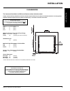
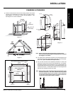
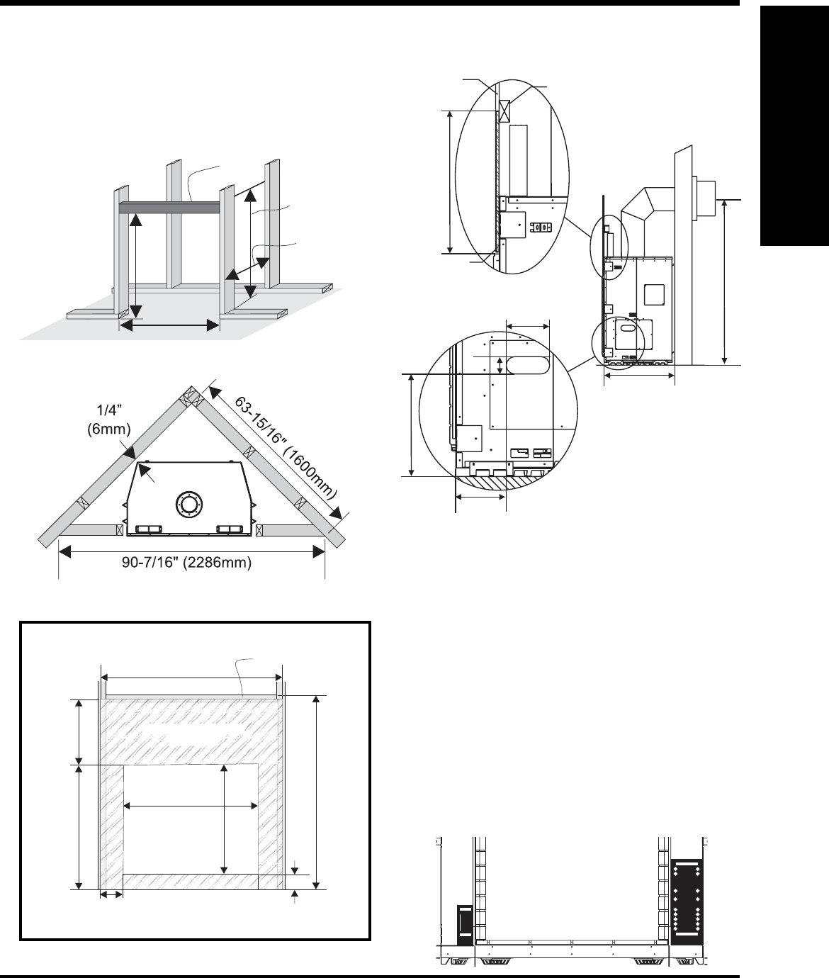
Diagram 1
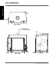
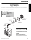
1) Frame in the enclosure for the unit with framing material. The framed
opening for the assembled kit is 50-3/4" high x 52" wide x 26-1/2"
deep (1289mm x H 1321mm W x 673mm D). See Diagram 1. Also
see Diagram 2 for corner installations.
Note: When constructing the framed opening, please ensure
there is access to install the gas lines when the unit is installed.
See diagram 3 for details.
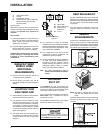
2) For exterior walls, insulate the enclosure to the same degree as the
rest of the house, apply vapour barrier and drywall, as per local instal-
lation codes. (Do not insulate the fi replace itself.)
3) The unit does not have to be completely enclosed in a chase. The
clearance on top of the unit from the top standoffs is 0" so combusti-
ble building materials can be laid directly on top of the standoffs. You
must maintain clearances from the vent to combustible materials: See
"Clearances" section. Combustible materials can be laid against the
side and back standoffs and the stove base.
FRAMING & FINISHING
26-1/2”
(673mm)
6”
(152mm)
5”
(127mm)
2”
(51mm)
76” (1930mm)
12-1/4” (311mm)
17-1/2” (445mm)
Header
(On Edge)
Drywall
Non-Combustible
Material
50-3/4"
(1289mm)
52”
(1321mm)
Min. 26-1/2"
(673mm)
83"
(2108mm)
Header
(On Edge)
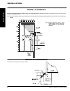
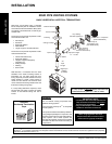
Diagram 2
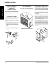
Diagram 3
Non-Combustible Requirements
52-1/2"
(1334mm)
10-5/16"
(254mm)
3"
(76mm)
35-1/16”
(891mm)
17-7/16"
(443mm)
32-1/16”
(814mm)
33-1/8"
(838mm)
53-3/4"
(1365mm)
Non-combustible
Material
Stud
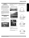
Note: When installing this fi replace there are two warnings on the
front face of the unit. The areas indicated here are painted
black and indicate that no nails, screws, or other punctures
can be made at these points as there are sensitive electronic
components directly behind these markings.
HERE
DONOT
NAIL
HERE
NAIL
NO