


16
Regency FG39 FireGenie Freestanding Gas Stove
INSTALLATION
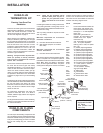
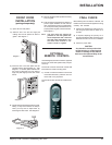
GAS CONNECTION
The gas line should be rigid pipe. Copper may
also be used if approved by AS5601-2004.
The gas connection at the valve is 1/2 male. For
minimum and maximum supply pressure see the
System Data Table.
GAS PIPE PRESSURE
TESTING
The appliance must be isolated from the gas
supply piping system by closing its individual
manual shut-off valve during any pressure
testing of the gas supply piping system at test
pressures equal to or less than 1/2 psig. (3.45
kPa). Disconnect piping from valve at pres-
sures over 3.45 kPa (14" w.c.).
The manifold pressure is controlled by a regu-
lator built into the gas control, and should be
checked at the pressure test point.
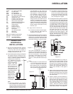
Note: To properly check gas pressure,
both inlet and manifold pressures
should be checked using the valve
pressure ports on the valve.
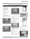
1) Make sure the valve is in the "OFF" position.
2) Loosen the "IN" (# 3) and/or "OUT" (# 4)
pressure tap(s), turning counterclockwise
with a 1/8" (3mm) wide flat screwdriver.
3) Attach manometer to "IN" and/or "OUT"
pressure tap(s) using a 5/16" (8mm) ID
hose.
4) Seal and or check the pilot outlet (# 8)
5) The pressure check should be carried out
with the unit burning and the setting should
be within the limits specified on the safety
label.
6) When finished reading manometer, turn off
the gas valve, disconnect the hose and
tighten the screw (clockwise) with a 1/8"
(3mm) flat screwdriver. Screw should be
snug, but do not over tighten.
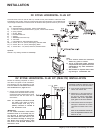
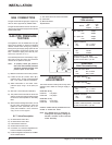
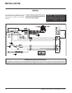
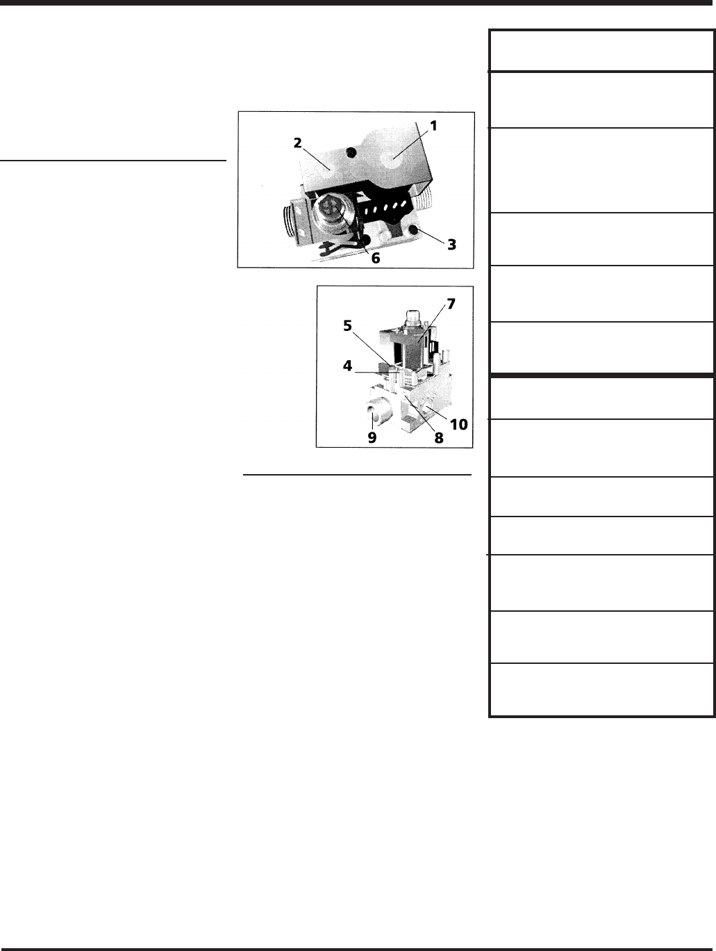
S.I.T. Valve Description
1) On-Off Solenoid Valve EV1
2) On-Off Solenoid Valve EV2
3) Inlet Pressure Test Point
4) Outlet Pressure Test Point
5) Connection for Pressure Regulator/Com-
bustion Chamber Compensation
6) Pressure Regulator for Minimum and Max-
imum Outlet Pressure
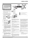
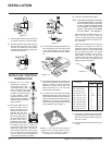
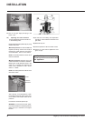
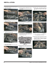
AERATION
ADJUSTMENT
The burner aeration is factory set but may need
adjusting due to either the local gas supply or
altitude.
FG39 with 40 mj.
FG39-NG Fully Open
FG39-LPG Fully Open
FG39 with 31 mj.
FG39-NG 6 mm Open
FG39-LPG 10 mm Open
Caution: Carbon will be produced if the air
shutter is closed too much.
Note: Any damage due to carboning re-
sulting from improperly setting the
aeration controls is NOT covered
under warranty.
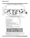
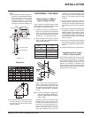
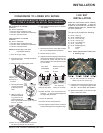
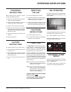
Burner Inlet Orifice Sizes:
NG LPG
Burner #32 #50
2.95mm 1.78mm
Max. Input NG 40 Mj/h
LPG 38 Mj/h
Min. Input NG 20 Mj/h
LPG 19 Mj/h
Supply Pressure
NG min. 1.13 kPa
LPG min. 2.75 kPa
Manifold Pressure
NG .94 kPa
LPG 2.55kPa
Electrical: 240 V. 1.13A 60Hz.
Circulation: 2 speed fan, 125/75 CFM.
Log Set: Ceramic fiber, 7 per set.
System Data
FG39 Converted to 31mj.
Burner Inlet Orifice Sizes:
NG #37 2.65mm
LPG #52 1.6mm
Max. Input - NG/LPG
31 Mj/h
Min. Input - NG/LPG
16 Mj/h
Supply Pressure
NG min. 1.13 kPa
LPG min. 2.75 kPa
Manifold Pressure
NG .89 kPa
LPG 2.55kPa
Electrical: 240 V. 1.13A 60Hz.
Circulation: Variable speed fan, 125/75 CFM.
Log Set: Ceramic fiber, 7 per set.
System Data
FG39 with 40mj.
7) Gas Outlet Pressure Electric Modulator
8) Pilot Outlet
9) Main Gas Outlet
10)Side Outlet