


F37 Regency
®
Rear Flued Room Sealed Freestanding Gas Heater 9
INSTALLATION
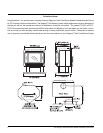
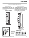
FLUEING ARRANGEMENTS - VERTICAL TERMINATIONS
for both Residential & Manufactured Homes/Mobile Homes
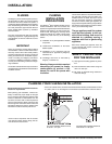
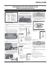
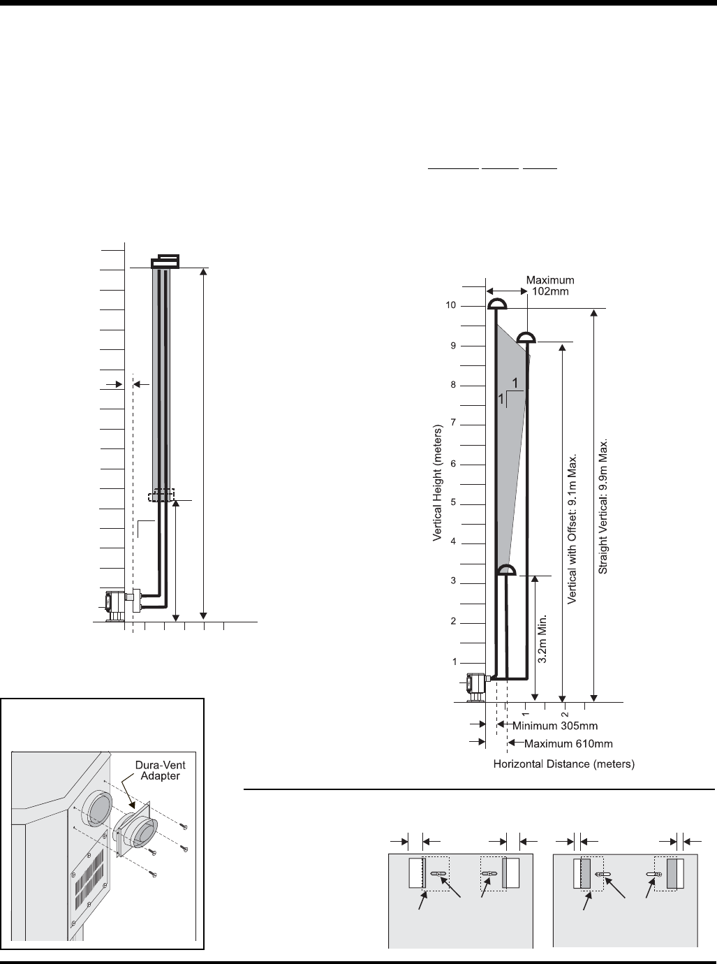
Offset to Vertical Terminations
If connecting to a Dura-Vent system,
the Adapter to Dura-Vent # 640-994
is required.
Vertical Terminations
with Co-linear Flex System
The shaded area in the diagram shows the allowable vertical
terminations installed in a masonry chimney. All vertical fl ue instal-
lations require the Flue Restrictor to be set to 32mm open. All Vertical
Flue Terminals must be Simpson Dura Vent (Abey Australia) DV 980
MAS (Australian Modifi ed.)
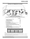
Vertical Terminations
using Dura-Vent Flueing System
The shaded areas in the two diagrams below show all allowable com-
binations of straight vertical and offset to vertical runs with vertical
terminations. Maximum one 90
o
elbow. All vertical and offset to vertical
fl ue installations require Flue Restrictor to be set to 32mm open. If the fl ue
is ENCLOSED in a chase (min. size 229mm x 229mm) maintain a 32mm
clearance to combustibles. All Vertical Flue Terminals must be Simpson
Dura Vent (Abey Australia) DV 980 MAS (Australian Modifi ed.)
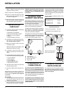
Straight Vertical Terminations
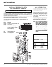
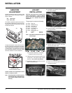
Flue Restrictor Position
Vent Restrictor
Vent
Restrictor
Plate
Vent Restrictor
(fully open)
Vent
Restrictor
Plate
44.5mm 44.5mm
32mm 32mm
To set the Flue restriction
as indicated in the diagram,
simply loosen the screws
and push the fl ue restrictor
plate to the correct position.
Tighten the screws.
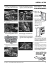
216mm
9.1m Max.
3.2m Min.
1
1
1
2
4
5
6
7
8
2
1
3
9
Horizontal Distance (meters)
Vertical Height (meters)