


22
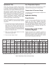
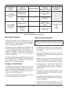
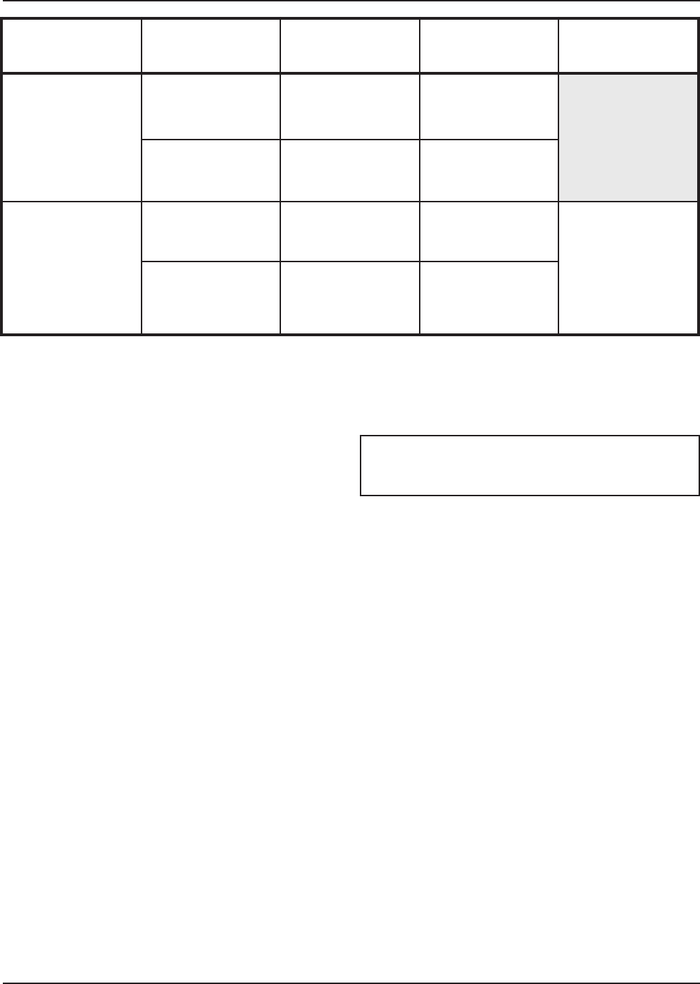
Table I: Venting Category Requirements
Combustion Air
S
upply
Exhaust
C
onfiguration
Venting Category
Certified
A
ppliance Material
Combustion Air
I
nlet Material
From Inside
Building (Non-Direct
Venting)
Vertical Natural
Draft Venting
I
Type B or any
C
ategory I Venting
System*
Horizontal
Thru-wall
Venting
III
Stainless Steel
(Gas Tight)
From Outside
Building (Direct
Venting)
Vertical Venting I
Type B or any
Category I Venting
System*
Galvanized Steel
PVC
ABS
CPVC
Horizontal
Thru-wall
Venting
III
Stainless Steel
(Gas Tight)
*As defined in the latest edition of the NFGC, or in Canada, the B149.
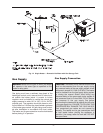
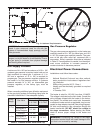
Barometric Damper
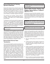
A barometric damper may be required when vent
heights exceed 25 feet or when the draft is greater
than -0.08 in. WC. In these installations, a barometric
damper (single acting) is required.
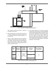
The damper should be installed NO CLOSER than 18
in. from the discharge of the unit and no closer than 18
in. from a combustible ceiling. The damper can be
installed in horizontal or vertical runs of vent pipe as
necessary. Installation in a bull-head tee is acceptable
as shown in the NFGC.
The weights on the damper should be adjusted per the
damper manufacturer’s instructions for proper opera-
tion, to maintain –0.01 to –0.08 in. WC, 12 in. from the
heater outlet, at all firing conditions.
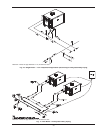
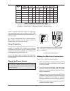
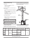
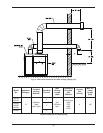
Support of Vent Stack
The weight of the vent stack or chimney must not rest
on the heater vent connection. Support must be pro-
vided in compliance with applicable codes. The vent
should also be supported to maintain proper clear-
ances from combustible materials.
Use insulated vent pipe spacers where the vent pass-
es through combustible roofs and walls.
Vent Terminal Location
1. Condensate can freeze on the vent cap. Frozen
condensate on the vent cap can result in a blocked
flue condition.
2. Give special attention to the location of the vent
termination to avoid possibility of property damage
or personal injury.
3. Gases may form a white vapor plume in winter.
The plume could obstruct a window view if the ter-
mination is installed in close proximity to windows.
4. Prevailing winds, in combination with below freez-
ing temperatures, can cause freezing of
condensate and water/ice build-up on buildings,
plants or roofs.
5. The bottom of the vent terminal and the air intake
shall be located at least 12 in. above grade, includ-
ing normal snow line.
6. Un-insulated single-wall metal vent pipe shall not
be used outdoors on cold climates for venting gas
utilization equipment.
7. Through-the-wall vents for Category II and IV
appliances and non-categorized condensing appli-
NOTE: During winter months check the vent cap
and make sure no blockage occurs from build up of
snow.