


20
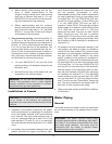
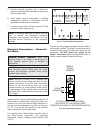
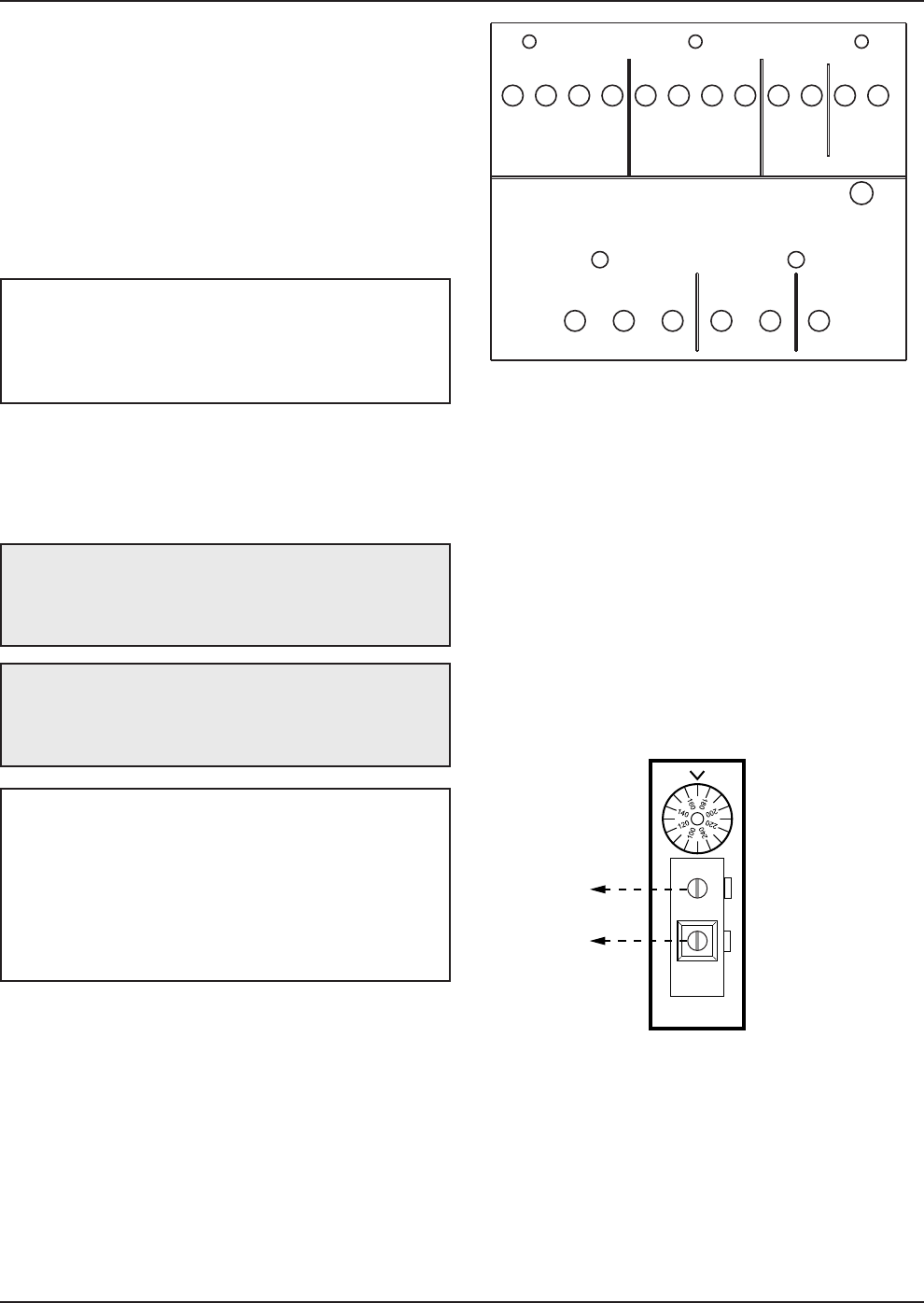
SINGLE
STAGE
TANKSTAT
STAGE 1
CONNECTION
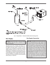
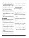
ATTACH STAGE 1 CONNECTIONS
ON HEATER TO THE SINGLE STAGE
TANKSTAT AS SHOWN IN THE DIAGRAM ABOVE.
Fig. 16: Single Stage Tankstat
Electrical Connections — Domestic
Hot Water
Installer action is required to electrically enable your Hi
Delta heater to operate after making the power con-
nections. You must use Terminal Block connections 1
through 4 for the temperature controller, as shown in
Fig. 15. This will be done based on the controller
option selected with your heater order.
For operation with a Temp-Tracker controller, refer to
the Temp-Tracker Installation and Operating
Instructions, Raypak Catalog number 5000.66 (P/N
241177).
CAUTION: Label all wires prior to disconnection
when servicing controls. Wiring errors can cause
improper and dangerous operation. Verify proper
operation after servicing.
DANGER—SHOCK HAZARD: Make sure
electrical power to the heater is disconnected to
avoid potential serious injury or damage to
components.
NOTE: Minimum 18 AWG, 105°C, stranded wire
must be used for all low voltage (less than 30 volts)
external connections to the unit. Solid conductors
should not be used because they can cause
excessive tension on contact points. Install conduit
as appropriate. All high voltage wires must be the
same size (105°C, stranded wire) as the ones on the
unit or larger.
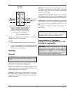
JUMPERED
W
HEN NOT USED
(OPTIONAL) JUMPERED
WHEN NOT USED
POWER IN
SAFETY VALVE PUMP
USE COPPER
CONDUCTORS ONLY
H
OT
COM
G HOT
COM
HOT
STAGE 1
STAGE 2
ENABLE /
DISABLE OR
SEQUENCER
INTERLOCK /
L
OUVER SW
ALARM
D
RY
CONTACTS
24V
24VR
CWS / CWR
FAN /DAMPER
(PILOT DUTY)
(OPTIONAL)
P/N 901935 REV 1
1
2
3
456
1
2
3
4
5
6
7
8
9
1
0
11 12
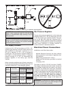
Consult the wiring diagram shipped with the heater in
the instruction packet. The Stage 1 connections are for
the remote tank control through the heaters 24 volt
transformer. DO NOT attach line voltage to the
Stage 1 connection. Before starting heater, check to
ensure proper voltage to heater and pump.
Fig. 15: Terminal Block Connections
5. Provide overload protection and a disconnect
means for equipment serviceability as required by
local and state code.
6. Install heater controls, thermostats, or building
management systems in accordance with the
applicable manufacturer’s instructions.
7. Conduit should not be used as the ground. There
must be a solidly wired ground.
NOTE: A grounding electrode conductor shall be
used to connect the equipment grounding
conductors, the equipment enclosures, and the
grounded service conductor to the grounding
electrode.