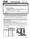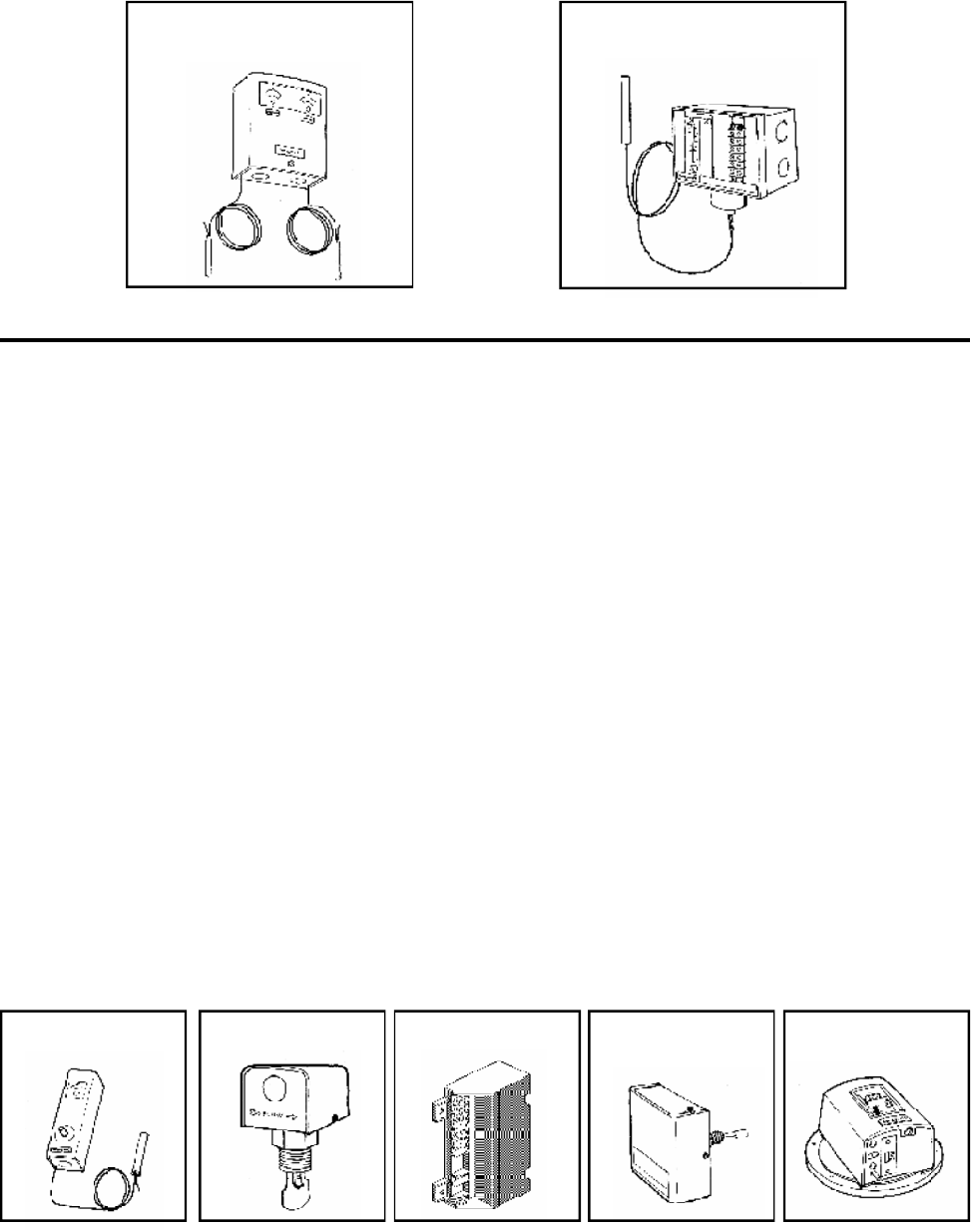
Models with Motorized Modulation: H2, H6, W2
Sizes 2100-4001 are equipped with a single motorized modulating valve controlled by a temperature
controller that offers full modulation down to 20% of rated input BTU.
LIMIT CONTROLS
1. HIGH LIMIT
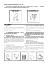
If boiler is equipped with a manual reset High Limit,
push the reset button and set the Limit(s) to 30° - 40°F
above operating temperature.
2. FLOW SWITCH
Dual purpose control shuts off boiler in case of
pump failure or low water condition.
3. 100% PILOT SAFETY
All standard boilers above 400,000 BTUH input are
equipped with pilot safety(ies), which close the main
valve within 8/10 of a second whenever the pilot flame
is interrupted. Pilot flame is automatically lit when the
device is powered. Unit performs its own safety check
and opens the main valve only after the pilot is proven
to be lit.
4. LOW WATER CUTOFF
The low water cut off automatically shuts down
burner whenever water level drops below probe. 90
second time delay prevents premature lockout due to
temporary conditions such as power failure or air pock-
ets.
5. HIGH AND LOW GAS PRESSURE SWITCHES
These switches sense either high or low gas pres-
sures and automatically shut down burners if abnormal
pressures exist.
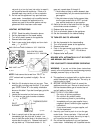
6. BLOCKED VENT SHUT-OFF SYSTEM
All indoor boilers below 300,000 BTUH input em-
ploy a blocked vent shut-off system designed to shut off
main burner gas in the event the venting system is
totally blocked.
In the event the blocked vent shut-off system is
actuated, do not attempt to place the boiler in operation,
but contact a qualified service agency.
7. FLAME ROLL-OUT
SAFETY SHUT-OFF SYSTEM
All boilers below 300,000 BTUH input employ a
flame roll-out safety shut-off system designed to shut-
off the main burner gas in the event of sustained flame
roll-out.
In the event the flame roll-out safety system is
actuated, do not attempt to place the boiler in operation,
but contact a qualified service agency
2
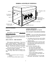
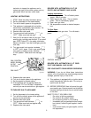
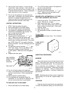
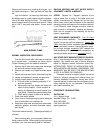
MANUAL RESET
HI LIMIT
FLOW SWITCH PILOT SAFETY LOW WATER
CUTOFF
HIGH OR LOW GAS
PRESSURE SWITCH
HIGH LIMIT AND
TEMP CONTROL
TEMP CONTROL
FOR MOTORIZED MODULATION
1 2
3
4 5
Fig # 9314 Fig # 9317 Fig # 8929 Fig # 9316 Fig # 9312


