


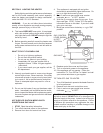
3. INSTALLATION PROCEDURES.
CODE REQUIREMENTS
Installation must be in accordance with local codes, or in the absence of local codes with the latest edition
of the National Fuel Gas Code, ANSI Z223.1, the National Electrical Code, ANSI/NFPA 70. For Canada, CAN/
CGA B149.1 and .2, and CSA C22.2 No. 1.
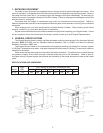
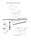
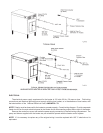
LEG INSTALLATION
Four (4) legs are supplied loose within the carton for installation at the site. This will provide the required six-
inch clearance off the floor. To install the legs, raise one end of the heater just high enough to allow the legs to
be screwed into the two corners of that end. Make sure each leg is tightened securely by hand. Lower the heater
gently to minimize any undue strain on the two (2) legs. Gently raise the other end, and repeat the same procedure
for the other two (2) legs. Rotate the lower section of each leg as necessary to level the heater in place.
Booster water heater should not be located in an area where water leakage will result in damage to the area
adjacent to it or to lower floors of the structure. Where such areas cannot be avoided, it is recommended that
a suitable catch pan, adequately drained, be installed under this heater. Do not install directly on carpeting.
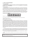
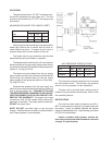
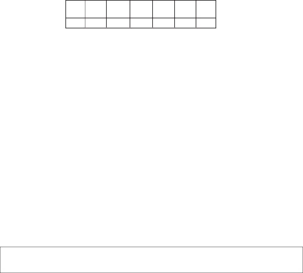
CLEARANCE REQUIREMENTS
Floor Top Left Right Front Back Vent
Side Side
* 0" 6" 6" Alcove 6" 1"
*Approved for installation on combustible flooring.
A front clearance of at least 24" is recommended for adequate service of burner-tray and controls.
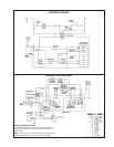
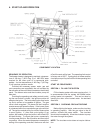
COMBUSTION/VENTILATION AIR
B195 COMBUSTION AIR ADJUSTMENT
This model is equipped with an air adjustment screw on the combustion air blower inlet. For natural gas the
opening is factory set at about 2.12" diagonal dimension, for propane gas the opening is 1.875" diagonal
dimension, which should be the proper setting for most installations. However, field conditions including unusual
gas characteristics may create a need for adjustment to achieve optimum performance. When the combustion
air setting is proper, there will be some lifting of the flames on some areas of the burner tile under cold start
conditions. After about five minutes of operation, the flames should settle down and blue tips should become
visible on some areas and orange glow on other sections of the burner tile. Lifting of flames beyond five minutes
would indicate too much combustion air. The adjustment screw should be turned clockwise to reduce the
combustion air supply until the lifting settles down. If the blue tips disappear and the entire burner surface
becomes radiant white, it indicates that there is not enough combustion air and the adjustment screw should be
turned counterclockwise to increase the combustion air opening until the blue tips and orange glow become
visible again.
The optimum excess air will result in CO
2 levels between 8 and 8.5% for natural gas and 9.2 to 9.7% for
propane. If a flue gas analyzing equipment is available, the opening can be adjusted to achieve this CO2 level.
Or, if an inclined manometer is available, pressure measured at the combustion air switch pressure tap, can be
set at -0.35" W.C. for natural gas and -0.60" W.C. for propane by means of the adjustment screw. Pressure at
this level will result in the proper CO2 levels mentioned above.
Again, the factory setting will be adequate for most field conditions and adjustment will not normally be
required.
CAUTION: A dusty kitchen environment combined with greasy laden air will clog the combustion air blower wheel
and cause premature failure of the heater. Combustion air must not be contaminated by corrosive chemical
fumes which can severely damage the heater.
4