


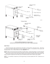

SECTION 4.
TESTING THE IGNITION SAFETY SHUT-OFF
The ignition system safety shut-off must be tested by
conducting the following method of tests:
a) With the system power off, manually shut off the
gas supply.
b) Turn power back on, observe the igniter start to
heat up and glow bright orange.
c) After about four (4) seconds, the gas valve is
energized, then de-energizes, after the third try the
module goes into a safety lockout a few sec-
onds later. Igniter will stop glowing and the R ed
LED on the module will start blinking.
d) Manually reopen the gas supply. No gas should be
flowing into the main burners. End of test.
e) To reset the system, momentarily shut off power
switch then turn it back on again. Igniter will start
to heat up and normal heating cycle will occur as
described in the sequence of operation on page
12.
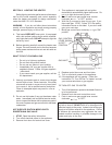
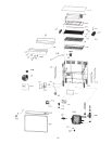
MAINTENANCE INSTRUCTIONS
1. The water pump motor and the combustion air
blower motor are permanently lubricated and re-
quires no other maintenance.
2. Venting system for this heater may be equipped
with high temperature plastic material rated for
operation at 480°F maximum. Check for signs of
deformation in the plastic vent pipes which will be
an indication of excessive temperature and abnor-
mal conditions in the venting system. Refer to the
instructions supplied by the vent pipe manufac-
turer.
3. The burner is made of ceramic material and oper-
ates in the infrared mode. When the burner is
operating properly very little blue flame will be
visible due to the incandescent brightness of the
ceramic material. This can be observed through
the glass observation port hole.
4. Depending on the condition of the kitchen environ-
ment, the burner and blower wheel may require to
be cleaned of lint or grease-laden dust. Inspect the
burner box every six months. Refer to the Servic-
ing Section related to burner removal.
BURNER INSPECTION/VISUAL
1. Shut-off electrical power and gas supply to the
heater.
2. Disconnect wiring to hot surface ignitor and sensor.
3. Remove screws on burner access panel.
4. Remove refractory block.
5. Visaully inspect burner tray panel.
6. Reverse above procedure to reinstall, checking
burner tray and seal to prevent leakage.
ADJUSTMENTS/REPLACEMENTS
OF COMPONENTS
CAUTION: Label all wires prior to disconnection when
servicing controls. Wiring errors can cause improper
and dangerous operation. Verify proper operation after
servicing.
DANGER - SHOCK HAZARD - Make sure electrical
power to the heater is disconnected to avoid potential
serious injury or damage to components.
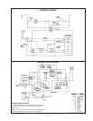
1. Gas Valve Replacement
a) Shut off electrical power and gas supply to the
heater.
b) Remove gas piping to gas valve inlet.
c) Remove front panel and leftside access panel.
d) Disconnect flex hose gas line.
e) Disconnect wiring connections to gas valve.
f) Remove (2) screws holding gas valve.
g) Reverse above procedure to reinstall.
2. Hot Surface Ignitor Replacement
a) Shut off electrical power and gas supply to the
heater.
b) Disconnect wiring leads to the igniter by pulling
apart plastic connector plugs.
c) Remove bracket holding ignitor cylinder.
d) Reverse above procedure to reinstall.
CAUTION: Silicon carbide ignitor is fragile and brittle.
Exercise extreme care in handling the assembly to
avoid damage.
3. Ignition Module Replacement
a) Shut off electrical power to the heater.
b) Remove control cover screws and open con-
trol compartment.
c) Disconnect wiring connections to module.
d) Remove screws (2) holding module.
e) Reverse above procedure to reinstall.
4. Transformer Replacement
a) Shut off electrical power to the heater.
b) Remove control cover screws and open con-
trol compartment.
c) Disconnect wiring connections from transformer
leads.
d) Remove screws (2) holding transformer.
e) Reverse above procedure to reinstall.
14