


28
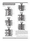
5. Remove the screws, retaining ring and rain gasket
from top of heater.
6. Remove the screws, flue collar and gasket from
the run side of the tee located in the flue box on
top of the heater.
7. Reverse the components and reattach in the new
location.
8. Make sure that the stainless steel cover, now lo-
cated on the run side of the tee, is sealed to avoid
any flue gas spillage.
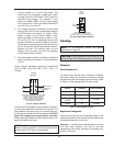
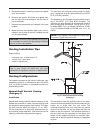
Venting Installation Tips
Support piping:
• horizontal runs - at least every 5 ft
• vertical runs - use braces
• under or near elbows
Venting Configurations
For heaters connected to gas vents or chimneys, vent
installations shall be in accordance with the NFGC
(U.S.), or B149 (Canada), or applicable provisions of
local building codes.
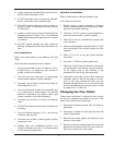
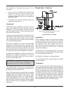
Natural Draft Vertical Venting
(Category I)
Installation
Natural draft venting uses the natural buoyancy of the
heated flue products to create a thermal driving head
that expels the exhaust gases from the flue. The nega-
tive draft must be within the range of -.01 to -.08 in.
WC as measured 12 in. above the appliance flue out-
let to ensure proper operation. Vent material must be
listed by a nationally recognized test agency.
CAUTION: The silicone vent gaskets must be prop-
erly reinstalled to prevent flue gas leakage. Replace
any torn or worn vent gaskets.
WARNING: Examine the venting system at least
once a year. Check all joints and vent pipe
connections for tightness, corrosion or deterioration.
The maximum and minimum venting length for Cate-
gory I appliances shall be determined per the NFGC
(U.S.) or B149 (Canada).
The diameter of vent flue pipe should be sized accord-
ing to the NFGC (U.S.) and B149 (Canada). The
minimum flue pipe diameter for conventional negative
draft venting using double-wall Type B vent is: 10 in.
for Model 992B; 12 in. for Models 1262B and 1532B;
14 in. for Models 2002B and 2072B; and 16 in. for
2342B.
The connection from the appliance vent to the stack
must be as direct as possible and shall be the same di-
ameter as, or larger than, the vent outlet. The
horizontal breaching of a vent must have an upward
slope of not less than 1/4 inch per linear foot from the
heater to the vent terminal. The horizontal portions of
the vent shall also be supported for the design and
weight of the material employed to maintain clear-
ances and to prevent physical damage or separation
of joints.
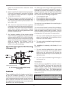
NOTE: A vent adapter (field-supplied) must be used
to connect Type B vent to the unit.
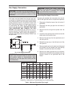
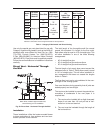
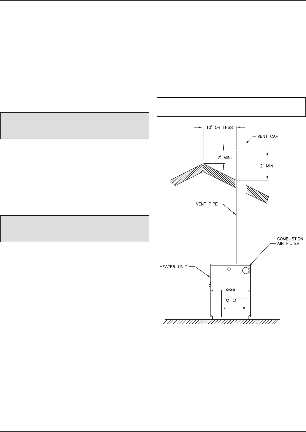
Fig. 27: Natural Draft Vertical Venting
(Category I)