


48
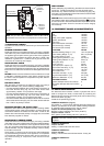
COMPONENT VALUE
Fan 120VAC
Pump 120VAC
3-way valve (field supplied) 120VAC
Ignition transformer 120VAC
Gas valve 120VAC
Room thermostat connection 24 Vdc
NTC sensor (dry contact) 10Kohm
NTC sensor (wet contact) 10Kohm
FUNCTION VALUE
Standard Heating Range °F (°C) 104-176 (40-80)
Floor Heating Range °F (°C) 68-113 (20-45)
CH limited power at 75% 15 Min
Heating OFF hysteresis °F (°C) SP+8 (+5)
Heating ON hysteresis °F (°C) SP-8 (-5)
Anti-cycle delay 3-min
Pump over-run 30-sec
Low output (min. output + %) Min+25
CO function max temp. °F (°C) 203 (95)
CO re-light temp. °F (°C) 167 (75)
CO function time 15-min
Flow NTC max temp. °F (°C) 203 (95)
High limit thermostat °F (°C) 221 (105)
Maximum differential °F (°C) 95 (35)
IGNITION CONTROL VALUE
Ignition attempts before L/O (lockout). 5
Re-ignition attempts after loss of flame
signal 5
14. COMPONENT VALUES & CHARACTERISTICS
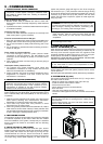
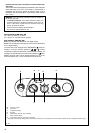
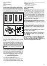
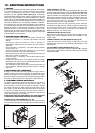
15. BOILER CONFIGURATION
The electronic board contains a series of jumpers that can be
used to configure the boiler; access these by loosening the
fasteners B and removing the control panel cover A after turning
off the main switch (Fig. 62).
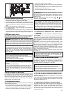
Locate the JP positioning (Fig. 63).
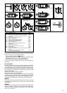
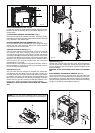
JUMPER IN POSITION 1 (Fig. 61):
The position nr. 1 of the jumper indicates the boiler heating tem-
perature; pre-selection of the most suitable heating temperatu-
re adjustment field according to the type of system.
Jumper not inserted (factory set) - case 1
Standard system (radiators) 104-176°F (40-80°C)
Jumper inserted - case 2
Floor system (radiant heating) 68-113°F (20-45°C).
NOTICE: The boiler has been factory-configured for standard
systems.
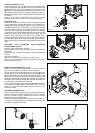
JUMPER IN POSITION 2:
Jumper inserted:
heating + indirect water tank with sensor
JUMPER IN POSITION 3:
Jumper inserted:
heating + indirect water tank with thermostat - factory set
JUMPER IN POSITION 4:
unused
13. ELECTRICAL CHECKS
Any electrical checks must be carried out by a ServiceTechnician
Qualified.
GROUND CONTINUITY TEST
Isolate the boiler from the electrical supply, and using a suitable
multi-meter carry out a resistance test. Connect test leads between
an appliance ground point and the ground wire of the appliance
supply cable. The resistance should be less than 1 OHM. If the
resistance is greater than 1 OHM check all ground wires and
connectors for continuity and integrity.
SHORT CIRCUIT CHECK
Isolate the boiler from the electrical supply, and using a suitable
multi-meter, carry out a short circuit test between the Live & Neutral
connections at the appliance terminal strip (Fig. 35). Repeat above
test on the Live & Ground connections at the appliance terminal
strip.
NOTICE: Should it be found that the fuse has failed but no fault
is indicated, a detailed continuity check will be required to trace
the fault. A visual inspection of components may also assist in
locating the fault.
POLARITY CHECK
With the boiler connected to the electrical supply and using a
suitable multimeter, carry out the following voltage tests:
- Connect test leads between the Live & Neutral connections at
the boiler terminal strip (Fig. 35). The meter should read
approximately 120VAC. If so proceed to next stage.
- Connect test leads between the Live & Ground connections at
the boiler terminal strip (Fig. 35). The meter should read
approximately 120VAC. If so proceed to next stage.
- Connect test leads between the Neutral & Ground connections
at the boiler terminal strip (Fig. 35). The meter should read less
than 1 VAC. If so polarity is correct.
REVERSED POLARITY OR SUPPLY FAULT
Repeat the above tests at the appliance isolator, if testing reveals
correct polarity and/or supply at the isolator, re-check wiring and
connections between the isolator and the boiler. If tests on the
isolator also reveal reversed polarity or a supply fault, consult the
local electricity supplier for advice.
RESISTANCE TO GROUND CHECK
Isolate the boiler from the electrical supply, and using a suitable
multi-meter carry out a resistance test. Connect test leads between
the Live & Ground connections at the appliance terminal strip
(Fig. 35). If the meter reads other than infinity there is a fault that
must be isolated, carry out a detailed continuity check to identify
the location of the fault.
These series of checks must be carried out before attempting
any troubleshooting procedures on the appliance. On completion
of any task that required the disconnection and re-connection of
any electrical wiring or component, these checks must be
repeated.
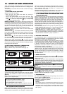
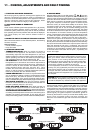
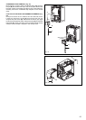
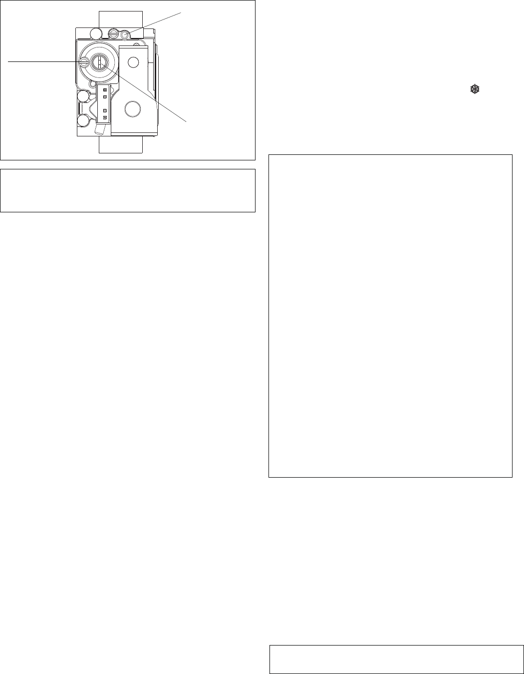
Fig. 60
Maximum
pressure
adjustment
screw
Minimum
pressure
adjustment
screw
Compensation
pipe connection
NOTE: The gas valve sticker “WARNING: VALVE IS NOT FIELD
SERVICEABLE” means the valve can be adjusted but not disassembled.
FAULT FINDING
Before attempting any faultfinding, the electrical checks must be
carried out. Isolate the appliance from the electrical supply.
Disconnect any external controls from terminal plug (Fig. 35),
and insert a jumper between the two wires at the room thermostat
connections (Fig. 35 ref. M4a).
NOTICE:
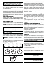
Restore the electrical supply to the boiler and turn the
main selector switch to the heating request position
. The boiler
should now function. Should the boiler fail to respond, the internal
fuses and connectors should be checked to ensure integrity
and continuity.