Consult the wiring diagram shipped with the heater in
the instruction packet or at the end of this section. The
stage-selector terminals are for the remote tank con-
trol through the heater’s 24 VAC transformer. DO NOT
attach any voltage to the stage-selector terminals.
Before starting the heater, check to ensure proper volt-
age to the heater and pump.
24
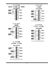
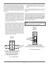
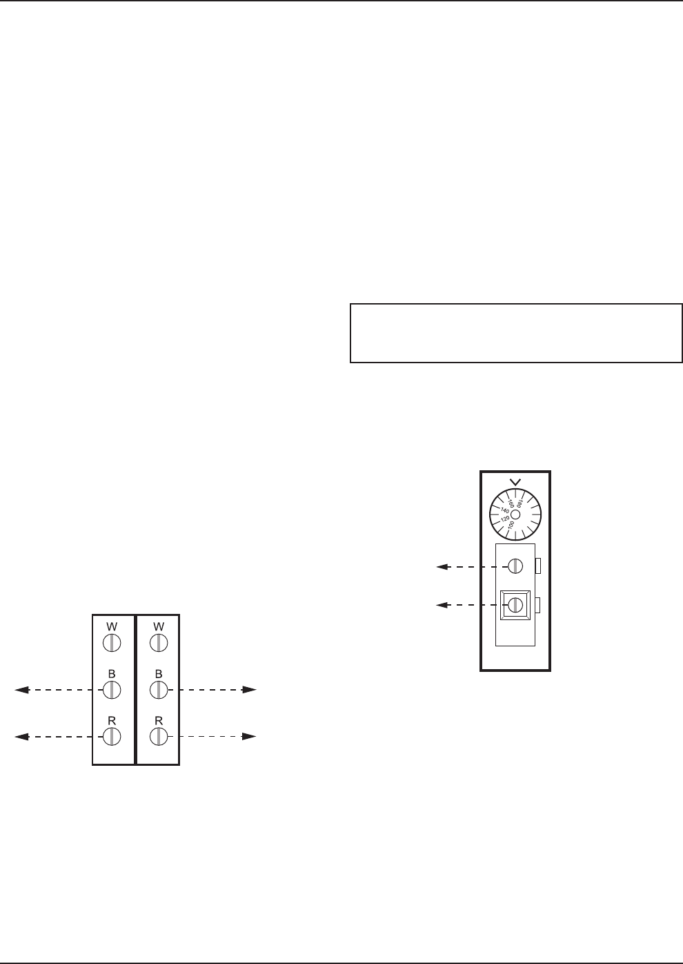
Fig. 23: 2-Stage Tankstat
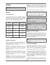
SINGLE
STAGE
TANKSTAT
STAGE 1
CONNECTION
ATTACH STAGE 1 CONNECTIONS
ON HEATER TO THE SINGLE STAGE
TANKSTAT AS SHOWN IN THE DIAGRAM ABOVE.
Fig. 24: Single-Stage Tankstat
Installer action is required to electrically enable your
heater to operate after making the power connections.
You must make a closed contact connection on Stage
1 connector of the Central Point Wiring (CPW) board
for temperature control connections. This will be done
based on the controller option selected with your
heater order.
1. For Closed-Loop Water-Source Heat Pump appli-
cations with fixed bypass, your heater should be
configured to operate in an on-off firing mode. This
means that you will connect a single-pole control
to stage one of the CPW board. Then jumper the
remaining firing stages. For example, if your
heater is a Model 1529B, you will jumper stages
two, three and four. Then your heater will either be
on at full fire, or it will be off.
2. For 2-stage controller connections, connect each
stage of the control to the corresponding stage of
the CPW board in the heater, i.e., stage 1 of the
heater to stage 1 of the control; stage 2 of the
heater to stage 2 of the control, as shown in Fig.
22 and Fig. 25. Set the operating control to the
set-point at which you want the heater to maintain.
Ensure that the sensing bulb of the control is at the
point in the system that will best maintain the tem-
perature you want. For example, when you are
heating a tank of water, you want the operating
control sensor bulb in the tank.
NOTE: If any of the original wire supplied with the
heater must be replaced, it must be replaced with
similar sized 105°C wire or its equivalent.
2-STAGE
TANKSTAT
STAGE 1
CONNECTION
STAGE 2 CONNECTION OR
STAGE 1 CONNECTION
OF HEATER 2
ATTACH STAGE 1 CONNECTIONS ON HEATER
TO STAGE 1 CONNECTION ON TANKSTAT.
ATTACH STAGE 2 CONNECTIONS OR
STAGE 1 CONNECTION OF HEATER 2
TO STAGE 2 CONNECTIONON TANKSTAT
AS SHOWN IN THE DIAGRAM.
3. For single-stage controller connections, attach the
stage 1 connections on heater 1 to the tankstat per
Fig. 26.
Heater must be electrically grounded in accordance
with the NEC, and CSA C22.1 C.E.C. Part 1 in
Canada.


