


9
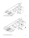
VENT DAMPER
NORMAL OPERATION SUMMARY
For safe, efficient operation, the vent damper and all flue product carrying areas of the appliance must
be checked annually, with particular attention given to deterioration from corrosion or other sources.
Check vent damper operation as follows:
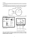
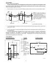
1. When the boiler is off, check that the vent damper position indicator points to the closed position, below.
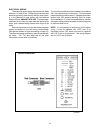
Fig. # 8181.0
FIG. 4- VENT DAMPER POSITION INDICATOR SHOWING OPEN & CLOSED POSITIONS.
2. Turn the thermostat or controller up to call for heat and check that the vent damper indicator points to the
open position, below.
3. Turn the thermostat or controller down again and check that the vent damper position indicator returns to
the closed position.
THE VENT DAMPER MUST BE INSPECTED AT LEAST ONCE A YEAR BY A TRAINED, EXPERIENCED
SERVICE TECHNICIAN. THE NAME OF THE PERSON WHO ORIGINALLY INSTALLED YOUR VENT
DAMPER IS SHOWN ON THE INSTALLATION LABEL. DAMPER MUST BE IN OPEN POSITION WHEN
BOILER MAIN BURNERS ARE OPERATING.
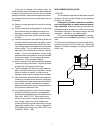
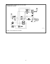
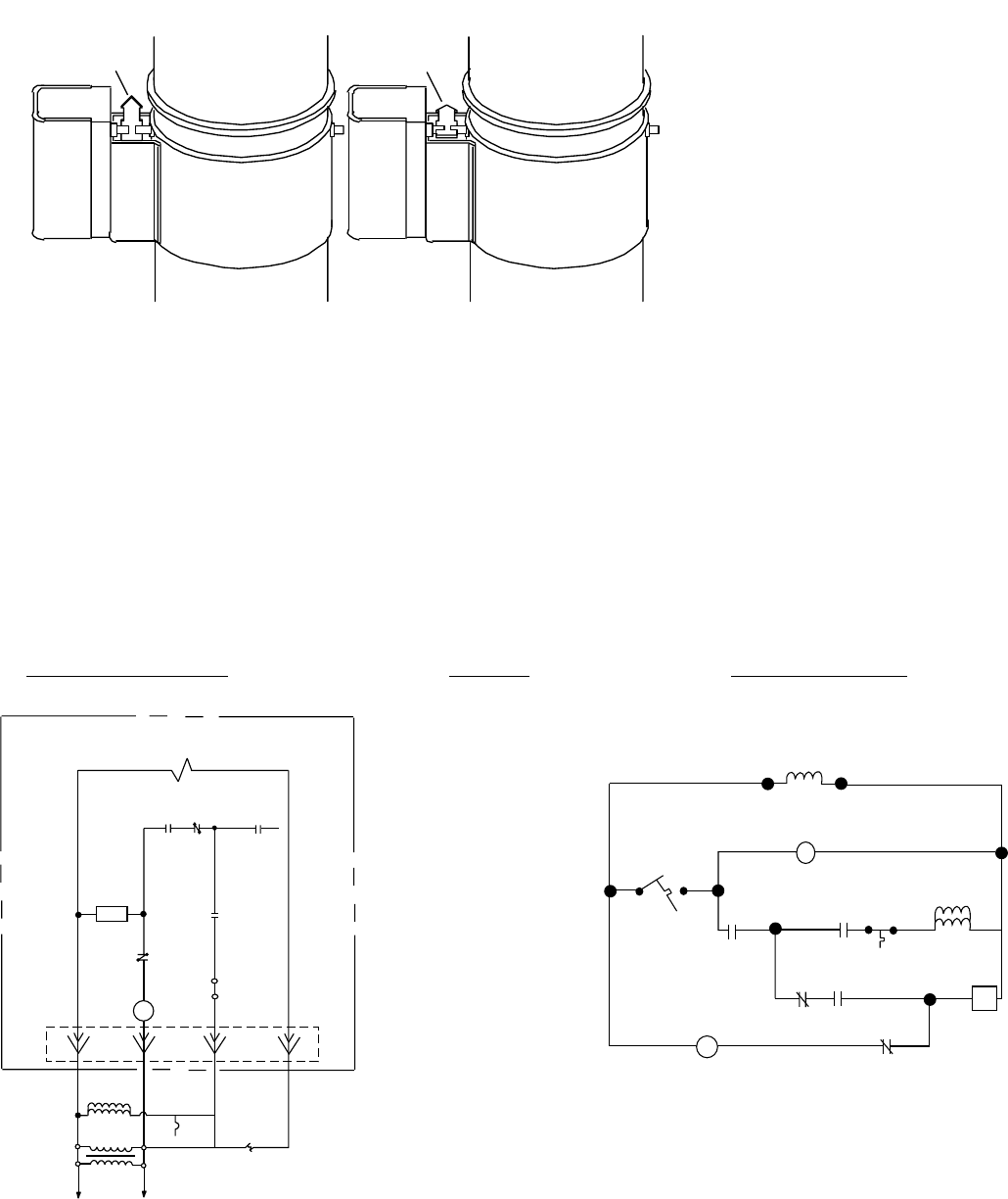
FLAIR DAMPER
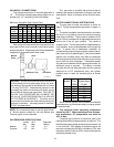
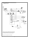
SYSTEM SCHEMATIC LEGEND LADDER DIAGRAM
M - Damper motor
R - Relay
ES - End Switch
SS1 - N/C Safety switch
SS2 - N/O Safety switch
contacts
TR - Transformer 120/24V
HL - High limit
GV - 24V gas Valve*
TH - Thermostat, heating,
low voltage
J - Jumper
* Note: Circuit shown with
damper in closed
position, no call
for heat.
Fig. #9002 Fig. #9003
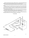
NOTE: To place vent damper in
the open position to allow burner
operation do the following:
Turn the power off, turn the damper
blade to fully open position (arrow
facing same direction as vent
pipe). Turn power on.
DAMPER
POSITION
INDICATOR
DAMPER
POSITION
INDICATOR
DAMPER OPEN DAMPER CLOSED
SS
R
2
SS
2
ES
R
SC
R
1
M
2
3
41
JUMPER
GV
24 VAC
TR
HL
L
L
12
120 VAC
60Hz
TH
1
R
2
4
3
J
SS
HL
GV
1
ES
R
2
SC
M
24 V AC
R
1
SS
2
TH