


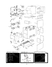
ADJUSTMENTS/REPLACEMENTS OF
COMPONENTS
DANGER - SHOCK HAZARD
Make sure electrical power to the boiler is disconnect-
ed to avoid potential serious injury or damage to com-
ponents.
1. Gas Valve Replacement
a) Shut off electrical power and gas supply to the
boiler.
b) Remove gas piping to gas valve inlet.
c) Disconnect wiring connections, pilot tubing
(when equipped).
d) Remove screws (2) holding the burner tray.
e) Slide burner tray out.
f) Remove gas valve bracket screws and bracket.
g) Unscrew gas valve from gas pipe.
h) Reverse above procedure to re-install.
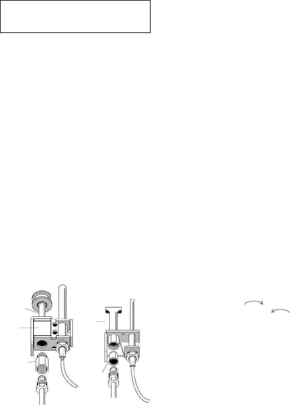
2. Pilot Burner Cleaning or Replacement (Standing
Pilot)
a) Shut off electrical power and gas supply to the
boiler.
b) Disconnect gas piping to gas valve.
c) Disconnect wiring connections to gas valve.
d) Remove screws (2) holding the burner tray.
e) Slide burner tray out.
f) Remove screw holding pilot lighter tube.
g) Remove screws (2) holding pilot bracket on the
burner tray.
h) Disconnect thermocouple and pilot tubing from
the gas valve.
i) Remove pilot burner from pilot bracket.
j) Remove pilot orifice and blow away lint or dirt.
Clean with wire or small brush.
NOTE: Make sure pilot orifice is clear, but do not
enlarge the hole.
k) Reverse above procedure to re-install.
3. Flame Roll-out Switch Replacement
a) Shut off electrical power to the boiler.
b) Remove wiring connections to switch.
c) Remove screws (2) holding the switch.
d) Reverse above procedure to re-install.
4. Vent Thermal Switch Replacement
a) Shut off electrical power to the boiler.
b) Remove wiring connections to switch.
c) Remove the screws (2).
d) Reverse above procedure to re-install.
5. Ignition Module Replacement
a) Shut off electrical power to the boiler.
b) Remove control cover screws and open control
compartment.
c) Disconnect wiring connections to module.
d) Remove screws (2) holding module.
e) Reverse above procedure to re-install.
6. Transformer Replacement
a) Shut off electrical power to the boiler.
b) Remove control cover screws and open control
compartment.
c) Disconnect wiring connections from trans-
former leads.
d) Remove screws (2) holding transformer.
e) Reverse above procedure to re-install.
7. Pump Relay Replacement
a) Shut off electrical power to the boiler.
b) Remove control cover screws and open control
compartment.
c) Disconnect wiring to the relay.
d) Remove screws (2) holding relay.
e) Reverse above procedure to re-install.
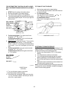
8. Adjustable High Limit Control
a) Shut off electrical power to the boiler.
b) Remove control cover screws and open
control compartment.
c) The control is factory set at 180°F. To reset to
another setting, use a small screw driver
and turn dial clockwise to lower the
temperature or counter-clockwise to
raise the setting.
d) To replace the limit control, disconnect the wir-
ing connections.
e) Remove screws (2) holding the limit control.
f) Remove upper access panel.
g) Remove the wedge or retaining clip holding
the sensing bulb in the control well in the in/out
header.
h) Pull out the sensing bulb carefully from the
control well.
i) Remove the limit control with capillary from
unit.
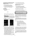
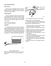
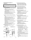
PILOT
HONEYWELL PILOT ROBERTSHAW PILOT
AIR
OPENING
ORIFICE
ORIFICE
PILOT
33
Fig.# 8045.2 Fig.# 8102.1