


22
Repair Section
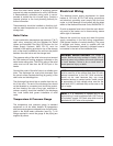
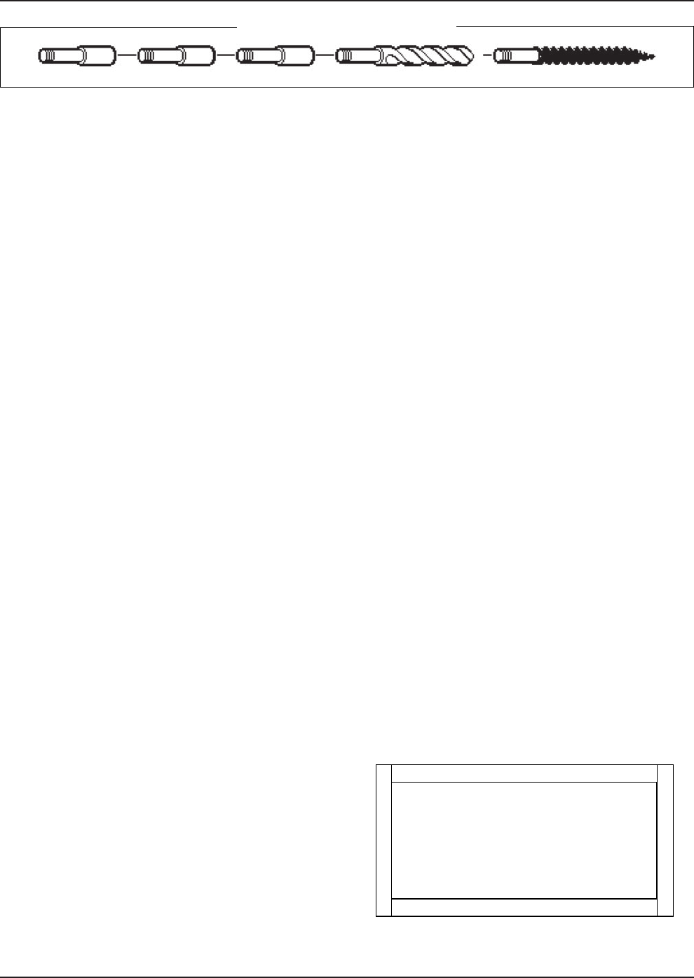
Tube Cleaning Procedure (Typical)
Establish a regular inspection schedule, the frequency
depending on the local water condition and severity of
service. Do not let the tubes clog up solidly. Clean out
deposits over 1/16" in thickness.
The heater may be cleaned from the side opposite the
water connections, without breaking pipe connections.
It is preferable, however, to remove both headers for
better visibility through the tubes and to be sure the
residue does not get into the system. Generally, you
do not remove the top pan or the heat exchanger .
After reaming with the auger, mount the wire brush
and clean out the debris remaining in the tubes.
Another method is to remove the heat exchanger,
ream tubes and immerse heat exchanger in non-inhib-
ited de-scale solvent.
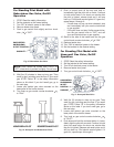
Heat Exchanger Removal
1. Shut water, gas and electricity off, close valves
and relieve pressure, remove relief valve. Remove
side inspection panels.
2. Remove top holding screws.
3. Remove draft diverter, lift and remove top and flue
collector on stack type models. Remove inspec-
tion panels.
4. Loosen bolts and disconnect flange nuts on inlet-
outlet header, loosen union(s) at gas pipe, and
slide heater away from piping until studs clear the
heater.
5. Remove heat exchanger corner brackets.
6. Remove combustion chamber clips at the four cor-
ners of the heat exchanger.
7. Lift heat exchanger straight up using caution not to
damage refractory.
Heat Exchanger Re-Assembly
1. Heat exchanger water header O-rings should be
replaced with new ones.
2. Install inlet-outlet and return water headers and
install header retainer nuts and torque nuts even-
ly.
3. Replace "V" baffles.
4. Install thermostat sensing bulbs in header wells
and replace bulb retaining clips.
5. Install inlet and return pipes in water headers
using pipe thread sealant.
6. Install water pressure relief valve, sensor probe,
and low water cutoff devices if so equipped.
7. Open water supply and return shut-off valves. Fill
heater and water piping system with water. Check
heater and piping system for leaks at full line pres-
sure. Run system circulating pump for a minimum
of 1/2 hour with heater shut-off.
8. Shut down entire system and vent all radiation
units and high points in system piping. Check all
strainers for debris. Expansion tank water level
should be at the 1/4 mark and the balance of the
tank filled with air (when using Air-X-Tank).
9. Install flue collector, jacket top and inspection pan-
els. Install top holding screws. Install draft diverter
and vent piping if so equipped.
10. If gas piping was disconnected, reconnect gas pip-
ing system and check for leakage using a soap
solution.
11. Check for correct water pressure and water level
in the system. Make sure that system pump oper-
ates immediately on the call for heat. The system
is ready for operation.
12. Within two (2) days of start-up, recheck all air
vents and expansion tank levels.
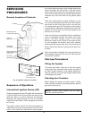
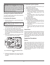
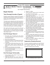
Combustion Chamber Removal
To remove combustion chamber you must first have
removed the heat exchanger. Unbolt metal combus-
tion chamber retainer from top and remove
combustion chamber panels individually.
Fig. 19: Refractory Panels—Top View
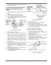
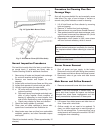
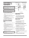
RAYPAK TUBE CLEANING KIT
hsurB eriWpiT edibraC htiw reguA )5( seceiP noisnetxE
Fig. 18: Raypak Tube Cleaning Kit