


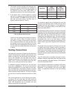
13
When this water heater system is supplying general
purpose hot water requirements for use by individuals,
a thermostatically controlled mixing valve is recom-
mended to reduce the risk of scald injury. Contact a
licensed plumber or the local plumbing authority for
further information.
Thermometer(s) should be installed so that they indi-
cate the water temperature at or near the outlet of the
storage tank.
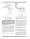
Relief Valve
A new combination temperature and pressure (T & P)
relief valve, complying with the Standard for Relief
Valves and Automatic Gas Shut Off Devices for Hot
Water Supply Systems, ANSI Z21.22, must be
installed in the opening provided on top of the storage
tank, at the time of installation. No valve is to be placed
between the relief valve and the storage tank.
The pressure rating of the relief valve must not exceed
the 160 maximum working pressure indicated on the
water heater rating plate. The BTUH rating of the relief
valve must not be less than the BTUH input of the
heater.
Connect the outlet of the relief valve to a suitable open
drain. The discharge line must pitch downward from
the valve to allow complete draining (by gravity) of the
relief valve and discharge line.
The discharge line should be no smaller than the out-
let of the valve. The end of the discharge line should
not be threaded or concealed, and should be protect-
ed from freezing. No valve of any type, restriction or
reducer coupling, should be installed in the discharge
line. Local codes shall govern installation of relief
valve.
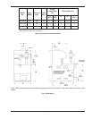
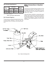
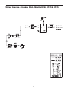
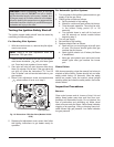
Temperature & Pressure Gauge
The temperature and pressure gauge is standard
equipment on all hot water heaters. All temperature
and pressure gauges are shipped loose for field instal-
lation in the outlet water connection (see Fig. 7). All
fittings required to mount the gauge to the piping are
supplied by others.
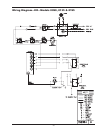
Electrical Wiring
The electrical power supply requirement for these
heaters is 120 volts, 60 Hz. Field wiring connections
and electrical grounding must comply with the local
codes, or in the absence of local codes, with the latest
edition of the National Electrical Code, ANSI/NFPA 70.
Provide a separate fused circuit from the main electri-
cal panel to the heater, and a disconnecting means
within sight of the heater.
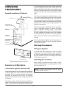
Remove the control box cover and make the power
supply connections in the field wiring compartment.
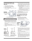
(See general location of controls drawing). The pump
is supplied and factory wired to operate with the
heater. The thermostat (tankstat) is shipped loose to
be installed in the tank at the installation site.
NOTE: If it is necessary to replace any of the
original wiring, it must be replaced with 105°C wire or
its equivalent, except 150° black wire which must be
replaced with 150° wire or its equivalent.
NOTE: Minimum 18 AWG, 105°C, stranded wire
must be used for all low voltage (less than 30 volts)
external connections to the unit. Solid conductors
should not be used because they can cause
excessive tension on contact points. Install conduit
as appropriate. All high voltage wires must be the
same size (105°C, stranded wire) as the ones on the
unit or larger.
WARNING: SHOCK HAZARD: Line voltage is
present. Before servicing tankstat or heater, turn off
electrical power to the heater at the main disconnect
or circuit breaker. Failure to do so could result in
severe personal injury or death.