


R
R
R
October 11,, 2005
250-6422D
Page 31
Castile Pellet Stove
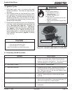
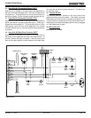
1. Convection Blower Replacement
a. Turn down thermostat, let appliance completely cool
and then unplug appliance before servicing.
b. The convection blower is located at the bottom rear
of the appliance and is housed inside a screen box.
Remove the 2 screws facing forward in the center of
the blower chamber at the very back of the appliance.
c. If an outside air kit is installed on the appliance, these
screws attach the intake air channel piece of the outside
air kit to the appliance. Remove the 2 screws and pull
backwards on the channel and it will slide down and
away from the appliance. The air channel, collar and
outside air hose will be removed as one piece.
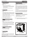
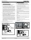
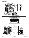
d. Remove the 4 screws that attach the blower housing to
the appliance, 2 on each side. Loosen all 4 screws, but
do not remove them. Lift the blower housing up slightly
and slide towards you. Figure 31.1.
e. Remove the left side panel by loosening 2 screws (do not
remove) and pull side panel away. Unplug the 2 black
blower wires by disconnecting the spade connectors.
f. To remove blower from the housing, remove 2 screws
in the front of the housing and very carefully bend the
2 housing sides out and bend the back of the housing
away from the blower. This allows for room to access
the back 2 screws and nuts (4 total) that is securing the
blower to the housing.
g. Remove blower and replace with new blower.
e. Re-install in reverse order.
D. Blower Replacement
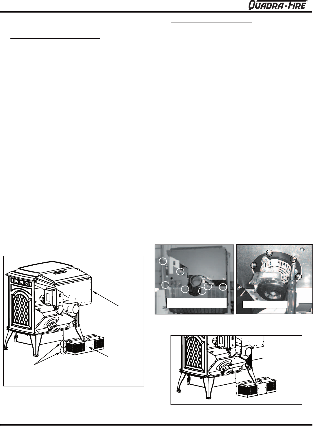
2. Exhaust Blower Replacement
NOTE: The convection blower must be removed
before the exhaust blower can be removed.
a. Turn down thermostat, let appliance completely cool and
then unplug appliance before servicing.
b Remove both side curtains by
loosening 2 screws (do
not remove) and pull side panels away.
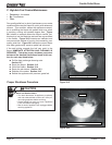
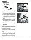
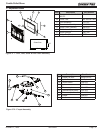
c. Remove 7 scr
ews from the back screen and pivot the top
of the screen toward you leaving the bottom attached to
stove. Figure 31.2.
d. Remove 2 screws to remove the thermostat block and
disconnect the 2 yellow wires.
e. Remove the 2 screws from the power inlet and rotate it
through the hole and out of the screen, leaving the wires
attached.
f. Disconnect the vacuum hose and both wires (orange
and red) from the vacuum switch attached to the rear
screen.
g. Remove both wires from exhaust blower (blue and
double white).
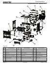
h. Remove 6 screws using a flathead screwdriver or a 1/4"
nutdriver. Retain screws for use on replacement blower.
Figure 31.3.
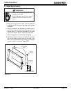
i. Remove exhaust blower and gasket.
j. Install new gasket and blower. Discard blower housing
if not needed.
k. Re-install in reverse order.
Figure 31.1
Figure 31.2
Loosen (do not remove) 2
screws on each side and lift
off blower housing
Remove left side
panel and discon-
nect blower wires
Convection Blower
& Housing
Exhaust
Blower
Remove 7 screws and bend top back
leaving it attached at the bottom.
Remove 6 screws
Figure 31.3
Figure 31.4