


R
R
R
October 11,, 2005
250-6422D
Page 17
Castile Pellet Stove
7
Appliance Set-Up
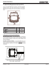
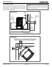
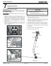
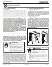
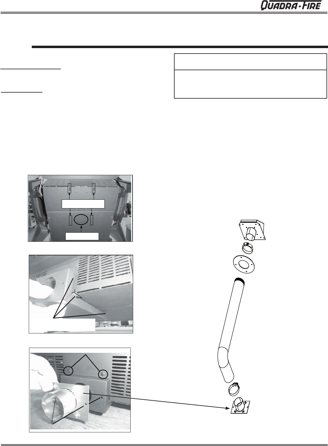
A. Outside Air Kit Instructions
Flex Hose
Hose Clamp
Collar Assembly
T
rim Rin
g
Terminatio
n
Cap Assembly
Hose Clamp
Parts Included in Kit: 1 piece of 2 inch x 3 foot flex hose,
2 hose clamps, 1 collar assembly,1 termination cap assem-
bly, 1 trim ring, 12 screws.
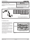
1. Measure distance from floor to air vent opening in appli
-
ance and mark location on wall.
Use saw to cut opening in wall. Cut a 2-1/2 to 3 inch
(64-76mm) opening on inside wall and a 3 to 3-1/2 inch
(76-89mm) opening on outside of house.
2. Use hose clamp to secure flex pipe to collar assembly.
3. Slide trim ring over flex pipe and run pipe through wall.
4. Attach hose to outside termination cap with second
hose clamp.
5. Secure termination cap to outside surface.
6. Secure trim ring to interior wall.
Tools Needed: Phillips headscrewdriver; wire cutters; hole
saw or jig saw.
CAUTION
Never draw outside combustion air from:
• Wall, floor or ceiling cavity
• Enclosed space such as an attic or garage
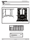
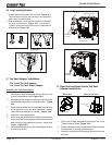
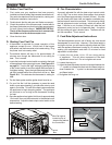
Mounting Slots
Pre-cut Hole
Align hooks with slots, push up
and slide forward
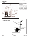
1. Figure 17.1 shows bottom of convection blower mount
and pre-cut air vent opening for reference only. Air
channel should be mounted with stove in upright posi-
Figure 17.1
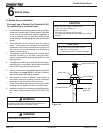
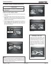
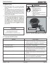
3. Secure air channel to appliance with 2 screws and
secure the collar assembly to the air channel with 2
screws. Figure 17.3.
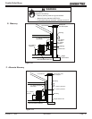
2. Align hooks in air channel with slots in convection
blower mount and ash box, Figure 17.2. Push up and
slide forward.
Attach air channel to stove with 2 screws
Attach collar to air channel with 2 screws
Figure 17.2
Figure 17.3
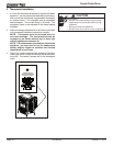
Figure 17.4