


Page 25
250-7061C December 10, 2004
4300 ACT Wood Stove Series
R
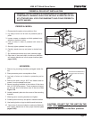
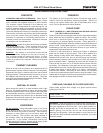
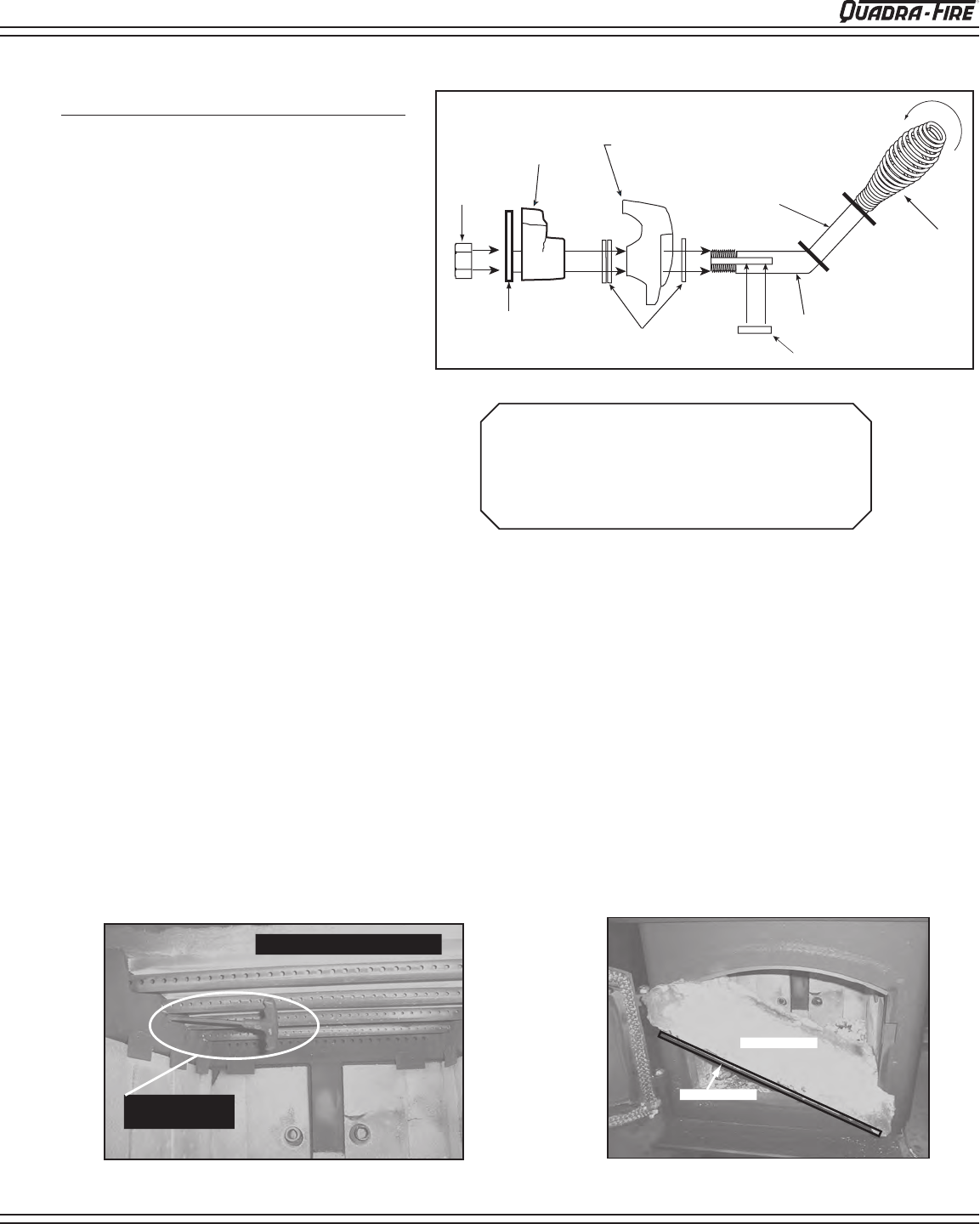
FIGURE 25C - Baffle and Ceramic Blanket .
Fiberboard Baffle
Ceramic Blanket
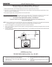
Allen wrench
on retainer bolt
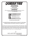
First tube has larger holes
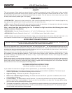
FIGURE 25B - Allen wrench on retainer bolt.
DOOR HANDLE ASSEMBLY
1. Remove all ash from the firebox, and extinguish all hot embers before disposal into a metal container.
2.
With a 3/16” allen wrench, remove the 2 front secondary combustion tube retainer bolts on the secondary air channel under the
end of the front tubes. See Figure 25B. NOTE: Soak the bolts with penetrating oil for at least 15 minutes before trying to remove
them.
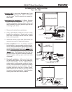
3. To remove the secondary combustion tubes, slide the tube to one side until one end is out of its hole. Then, while lifting that end of
the fiber board, pull the tube up over the secondary air channel and out of the hole at the other end.
NOTE: When replacing the secondary tubes, be sure the tube with the larger holes is placed in the front or your stove
will not operate properly.
4. Slide fiber board and ceramic blanket forward to front of stove, tilt down and slide to the door. Tilt to one side and slide both through
door at the same time. Keep them tilted as you lift it out of the door.
See Figure 25C.
5. To install the fiber board baffle and ceramic blanket, repeat steps 2 through 4 in reverse. Be sure that the fiber board baffle is pushed
back fully and the blanket is down flat. The front of the blanket should be flush with the front of the baffle.
NOTE: The baffle in the 4300 is 2700° Fiber Board. Removing hardware exposed to combustion processes can be frustrating.
If your reason for removing the baffle is simply to clean the chimney, you have alternatives which will save time and effort. Call a
qualified chimney sweep or an authorized Quadra-Fire dealer for details.
BAFFLE REMOVAL AND INSTALLATION
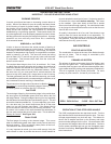
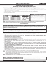
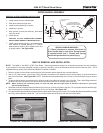
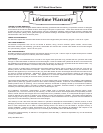
1. Install washer on door handle shaft.
2. Slide door handle through door.
3. Install second washer(s) as shown.
4. Install key in groove.
5. Align groove in latch cam with key; slide latch
cam over shaft.
6. Install locknut.
CAUTION! DO NOT OVERTIGHTEN LOCKNUT.
DOOR HANDLE NEEDS TO MOVE SMOOTHLY.
7. Install spring handle turning in a counter-clock-
wise motion on handle leaving a 3” (76mm)
clearance from bend in door handle rod to end
of spring handle. See Figure 25A.
SPRING HANDLE WARNING!
3” (76mm) clearance is required from bend in
Door Handle Rod to end of the Spring Handle.
If installed within that 3” (76mm) area, Spring
Handle will get hot and may cause injury.
SEE PAGE 20 FOR OPERATING INSTRUCTIONS
FIGURE 25A
Locknut
Door Cross Section
(example)
Latch Cam
Spacing
Washers
Square Key
Door Handle
Spring
Handle
3" (76mm) clearance
required from bend in Door
Handle Rod to end of Spring
Handle.
Secondary
Latch