


4300 ACT Wood Stove Series
Page 12 250-7061C December 10, 2004
R
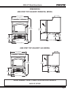
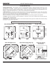
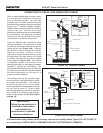
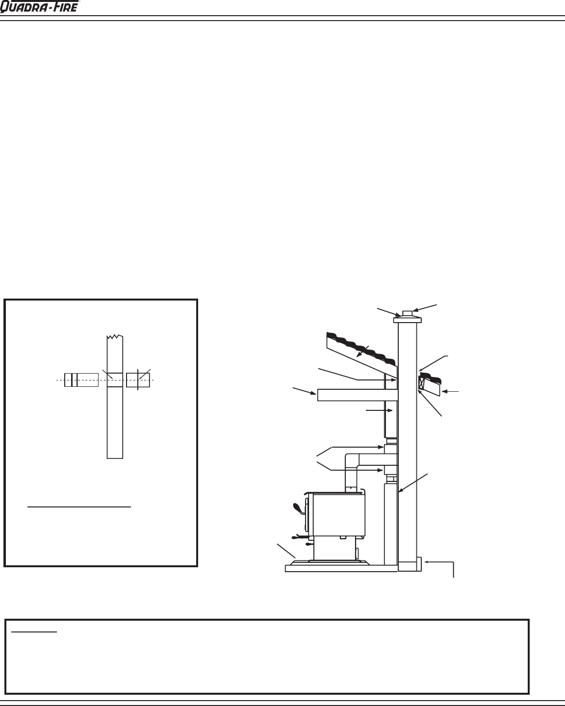
FIGURE 12B
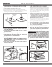
SOLID PACK CHIMNEY WITH METAL SUPPORTS AS A THIMBLE
For the method of installation to a masonry chimney shown in Figures 14A & 14B on page 14, it will be necessary to
purchase a 12” (305mm) long 8" (203mm) inside diameter, section of prefabricated listed solid pack chimney to use as a
thimble. Purchase a wall spacer, trim collar, and a wall band manufactured to fit the chimney section you purchase.
The safety features of this system are twofold: 1) A 2" (51 mm) air space between the chimney section and combustible
wall; and, 2) The 1" (25mm) air space around the chimney connector as it passes through the chimney section to
the chimney.
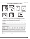
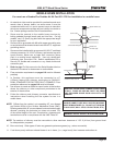
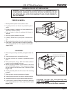
The location of the opening through the wall to the chimney must leave a minimum 18" (457mm) vertical clearance
between the connector pipe and the ceiling (or minimum recommended from pipe manufacturer) to prevent the
ceiling from catching fire.
Measure for the center-line as shown in Figure 12A below. Cut an opening in the wall large enough to accommodate the
outside dimension of the chimney section plus the minimum air space specified by its manufacturer. It may be necessary
to cut the wall studs and install a header and a sill frame to maintain the wall support. The hole in the chimney must have
at least an 8" (203mm) diameter fire clay liner or equivalent, secured with refractory mortar. If it is necessary to cut a hole
in the chimney liner, use extreme care to keep it from shattering.
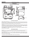
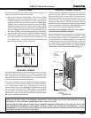
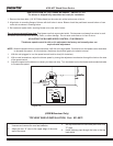
FLOOR
PROTECTOR
THIMBLE,
12" (305mm)
OF BRICK
CEILING
JOIST
COMBUSTIBLE
WALL
1" (25mm)
CLEARANCE
AIRTIGHT
CLEANOUT DOOR
FIRECLAY
FLUE
LINER WITH AIR
SPACE
SHEATHING
EAVE
1" (25mm) CLEARANCE
WITH FIRESTOP
RAFTER
FLASHING
CONCRETE CAP
WARNING! ALWAYS FOLLOW CHIMNEY CONNECTOR MANUFACTURER’S INSTRUCTIONS FOR PROPER INSTALLATION.
CHIMNEY CONNECTOR IS TO BE USED ONLY WITHIN THE ROOM, BETWEEN THE STOVE AND CEILING OR WALL, NEVER
PASSING THROUGH A COMBUSTIBLE CEILING OR WALL. THE CONNECTOR SHALL NOT PASS THROUGH AN ATTIC OR
ROOF SPACE, CLOSET OR SIMILAR CONCEALED SPACE, OR A FLOOR, OR CEILING. MAINTAIN MINIMUM CLEARANCES
TO COMBUSTIBLES AS REFERENCED ON PAGE 7.
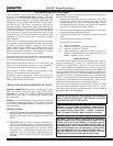
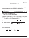
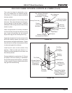
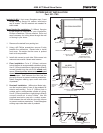
Center of Hole
Wa
ll
Center Line
Opening
Center Line
Add center-line measurement to depth
measurement of your floor protector. Mark
this combined measurement at correct wall
location for your installation, maintaining
minimum clearance to combustibles, and
mark wall for a 10" x 10" (254mm x 254mm)
square hole.
FIGURE 12A