Page 5
Minimum clearances to Combustible Materials (in inches and millimeters) for Quadra-Fire 1900 Standard Stove
Chimney &
Installation Clearance Connector A B C D E F G
Residential Standard Note 1 20(508) 25(635) 22(559) 18(457)* 15(381) 12(305) 52(1321)
Residential/Mobile Home Reduced Note 2 11(280) 20(508) 19(483) 9(229) 10(254) 9(229) 52(1321)
Alcove Standard Note 2 & 3 11(280) 20(508) 19(483) 9(229) 10(254) 9(229) 52(1321)
Minimum clearances to Combustible Materials (in inches and millimeters) for Quadra-Fire 1900 with top shield
Chimney &
Installation Clearance Connector A B C D E F G
Residential Standard Note 1 20(508) 25(635) 19(483) 18(457)* 15(381) 9(229) 44(1118)
Residential/Mobile Home Reduced Note 2 7(178) 18(457) 13(330) 6(152) 8(203) 3(76) 44(1118)
Alcove Standard Note 2 & 3 7(178) 18(457) 13(330) 6(152) 8(203) 3(76) 44(1118)
*Note: Dimension D (residential standard) can be 16 (406mm) in the United States.
Note 1: 6 (152mm) diameter single wall, minimum 24 MSG black or blued steel connector pipe with a listed factory-
built type HT chimney suitable for use with solid fuels or a masonry chimney.
Note 2: 6 (152mm) diameter double wall insulated connector pipe with listed factory-built type HT chimney or a
masonry chimney. (Mobile home venting system must be equipped with a rain cap and spark arrestor.) For installations
with a preexisting class A chimney system, a listed stainless steel chimney liner should be installed, or the existing
chimney examined by a chimney sweep for acceptable further use.
Note 3: Alcove specifications: Maximum depth of alcove shall be no more than 48 (1219mm). For additional alcove
information and clearances, refer to clearances to combustibles above.
NOTE: Unit is approved for use with listed double wall air-insulated chimney connector or elbows.
When locating your stove consider safety, convenience, traffic flow, and the fact that the stove will need a chimney and
chimney connector.
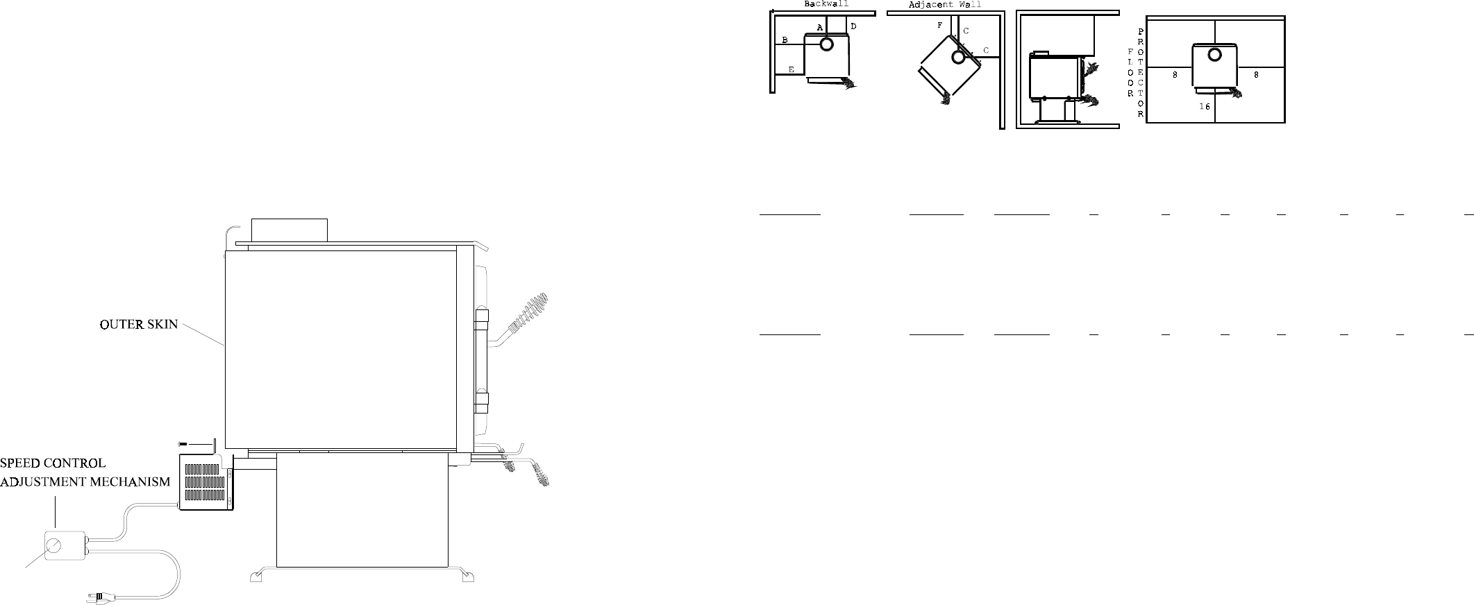
FLOOR PROTECTION: Floor protector must be noncombustible material, extending beneath heater and to the front/
sides/rear as indicated.
NOTE: A 3/8 (10mm) minimum thickness tile or equivalent is recommended, but not required.
NFPA 211: Use a noncombustible material with 1 (25mm) ventilated air space to reduce clearances. However, this is
not to exceed 50% of Quadra-Fires specified clearances.
NOTE: Must follow NFPA 211 spacing and materials to qualify. It is also subject to local jurisdiction.
AVOID FIRE: Maintain the designated clearances to combustibles. Insulation must not touch the chimney. You must
maintain the designated air space clearance around the chimney. This space around a chimney is necessary to allow
natural heat removal from the area. Insulation in this space will cause a heat buildup, which may ignite wood framing.
CLEARANCES TO COMBUSTIBLES (UL AND ULC)
FLOOR PROTECTOR: Floor
protector must be noncombustible
material or equivalent, extending
beneath heater and to the front/
sides/rear as indicated.
NOTE: A 3/8 (10mm) minimum
thickness tile or equivalent is
recommended, but not required.
G
8
Page 24
INSTALLATION OF OPTIONAL BLOWER
Part #831-1700
The blower is shipped fully assembled and ready for installation.
1. Remove three 1/4-20 (3/8 hex head) bolts from blower cover, and remove nutbar. Discard nutbar.
2. Using bolts, attach blower to lower rear of stove, as shown.
3. Plug blower cord into a grounded outlet. Do not remove ground prong from plug. Route power cord to
avoid heat from the stove, or other damage.
4. Adjust the blower speed control to the desired speed.
BLOWER SWITCH ADJUSTMENTS
The blower speed control for this unit is adjusted at the factory, and should not require further adjustment.
When the speed control is turned clockwise, it will click on to high speed. Turn the speed control clockwise to
decrease the speed. At full clockwise, the blower should blow gently, but should not stop.
STEPS FOR ADJUSTING THE BLOWER SPEED CONTROL
1. With the unit plugged in, turn the speed control knob to slow (full clockwise).
2. With a small screwdriver, adjust the blower speed by turning the adjustment mechanism through the hole on
the side of the speed control.
3. Adjust the speed so the blower runs slowly, but does not stop. Turn clockwise to slow the blower and
counterclockwise to increase the speed.
BLOWER SPEED CONTROL


