DURAWATT
®
ELECTRIC WATER HEATER
PV500-6 09/07 8
Sediment / Lime Scale Removal
Waterborne impurities consist of the particles of soil and sand which settle out and form a layer of sediment on the bottom
of the tank and adheres to heat exchange surfaces. The amount of calcium carbonate (lime) released from water is in
direct proportion to water temperature and usage. The higher the water temperature or water usage, the more lime
deposits are dropped out of the water. Lime accumulation not only reduces the life of the equipment but also reduces
efficiency of the heater.
T & P Relief Valve
The pressure relief valve should be checked at regular intervals by manually opening the valve. The openings inside the
valve may become restricted by a buildup of scale and become inoperative. If the valve does not open and close properly
and does not blow off internal pressure when tested, it must be replaced. Shut down heater, relieve internal pressure and
replace relief valve with a like kind or one meeting the requirements stated on the rating decal located adjacent to the
relief valve mounting location.
Low Water Cut-Off
The standard low water control is electronic. Inspection should be made of the electrode on water heaters equipped with
electronic low water devices.
Electrical Connections
Check all electrical connections approximately one to two weeks after initial start-up to assure tightness. Heating and
cooling from operation can loosen connections. Visually inspect wire terminal points for any discoloration on a monthly
basis. Discoloration is likely due to a loose connection at the point nearest discoloration. Check Contactors periodically
and clean if necessary and repair or replace pitted points caused by foreign particles. Check Fuses periodically for
continuity and replace if necessary with the same dual-element type.
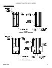
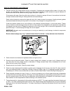
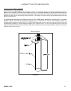
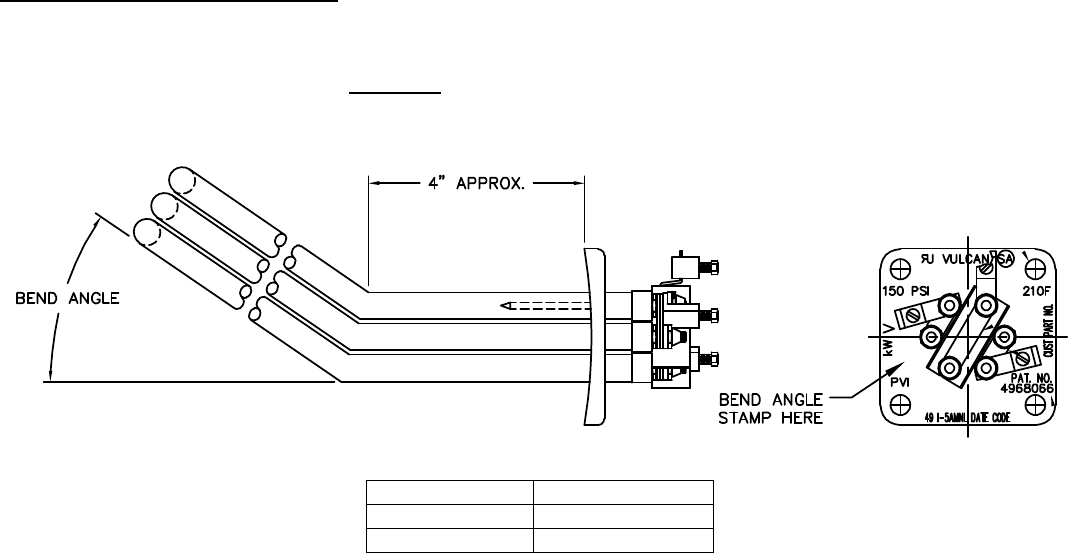
REPLACING ELECTRIC ELEMENTS
Some electric heating elements installed in dished heads may be factory bent to allow clearance from adjacent elements.
Replacement elements must be identical to the original equipment installed. The Bend Angle Stamp # is required for all
replacement electric element requests. Important
: Install the element facing away from the center of the head.
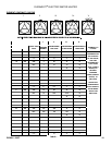
FIGURE 4
BEND ANGLE STAMP
25° #1
18° #2
FIGURE 4
Note: No stamp on element flange means that element is not bent.
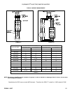
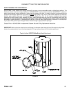
Typical Electric Element