


10
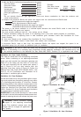
2. Open gas supply tank valve.
3. Make sure control knob of heater is
in the OFF position.
4. Check all joints from equipment
shutoff valve to control valve
(LP GAS see Figure 9.1 NATURAL
GAS see Figure 9.2). Apply
mixture of liquid soap and water
to gas joints. Bubbles forming
show a leak.
5. Correct all leaks at once.
6. Light heater (see Operating
Heater). Check all other internal
joints for leaks.
7. Turn off heater (see To Turn Off
Gas Appliance).
WARNING: Failure to position
the parts in accordance with these
diagrams or failure to use only parts
specifically approved with this heater
may result in property damage or
personal injury.
CAUTION: After installation
and periodically thereafter, check to
ensure that no flame comes in
contact with any log. With the heater
set to High, check to see if flames
contact any log. If so, reposition logs
according to the log installation
instructions in this manual. Flames
contacting logs will create soot.
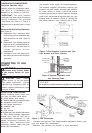
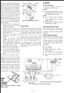
It is very important to install the logs
exactly as instructed. Do not modify
logs. Only use logs supplied with
heater.
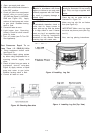
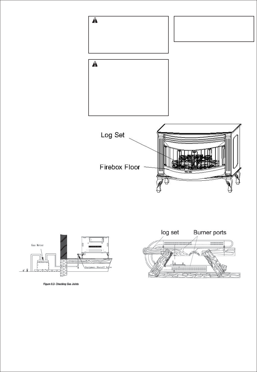
Place log set on grate to fit as
illustrated in Figure 10.
Make sure log sits flat on firebox
floor (see Figure 10).
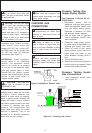
IMPORTANT: Make sure log does
not cover any burner ports (see Fig-
ure 11).
Also, see log placing instructions.
Figure 10 -Installing Log Set
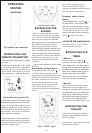
Figure 11 -Installing Log Set (Top View)
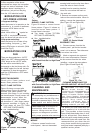
Figure 9.2 -Checking Gas Joints
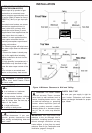
Test Pressures Equal To or
Less Than 1/2 PSIG(3.5 kPa)
1. Close equipment shutoff valve
(see Figure 8).
2. Pressurize supply piping system
by either using compressed air or
opening natural supply tank
valve.
3. Check all joints from gas meter to
equipment shutoff valve(see
Figure 9). Apply mixture of liquid
soap and water to gas joints.
Bubbles forming show a leak.
4. Correct all leaks at once.