


48
© Baxi Heating UK Ltd 2008
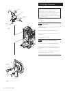
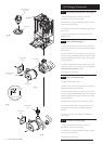
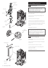
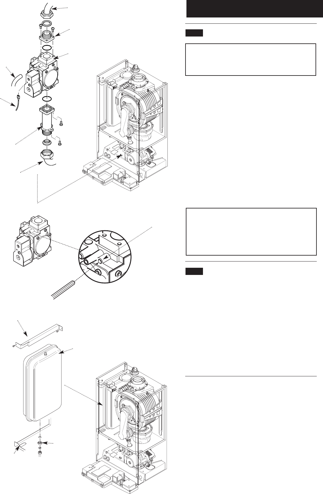
Gas Valve
Valve
Inlet Pipe
Gas Feed
Elbow
Fig. 103
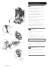
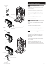
Ignition Lead
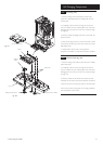
Expansion Vessel
Boiler Chassis
Lock Nut
Fig. 104
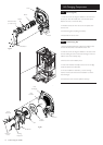
Retaining Bracket
Sensing Pipe
Venturi Inlet
Pipe
Outlet Adaptor
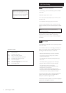
14.0 Changing Components
14.23
Gas Valve (Fig. 103)
IMPORTANT: After replacing the valve the CO
2
must be
checked and adjusted as detailed in Section 15.0
Combustion Check. Only change the valve if a suitable
calibrated combustion analyser is available.
1. Turn the gas cock off and undo the nut on the gas feed
elbow under the boiler.
2. Remove the screws securing the inlet pipe flange to the
boiler bottom panel.
3. Pull off the earth lead and sensing pipe.
4. Undo the nut on the venturi inlet pipe and slacken the nut
on the venturi. Ease the pipe aside and remove the gas valve.
5. Remove the outlet adaptor and inlet pipe and transfer them
to the new valve. Examine the ‘O’ ring seals, replace if
necessary.
6. Reassemble in reverse order.
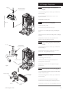
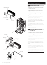
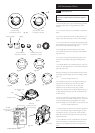
NOTE: To assist the boiler to light prior to final setting,
use a suitable hexagon key to wind out the Gas/Air
adjustment screw until it is flush with the valve body, then
turn the screw 4 full turns clockwise (Fig. 103a). If the
boiler will not light, or the correct CO
2
cannot be achieved
contact the ‘heateam’ technical helpline.
14.24 Expansion Vessel (Fig. 104)
1. Drain the primary circuit and undo the nut on the vessel
connection pipe.
2. Undo and remove the locknut securing the vessel spigot to
the boiler air box.
3. Remove the bracket and vessel from the boiler.
4. Locate the retaining bracket on the upper flange of the
vessel and fit to the boiler.
5. Reassemble in reverse order.
Fig. 103a
Gas/Air
Adjustment Screw