


29
10.0 Installation
© Baxi Heating UK Ltd 2008
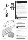
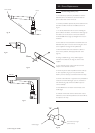
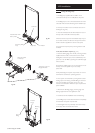
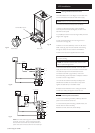
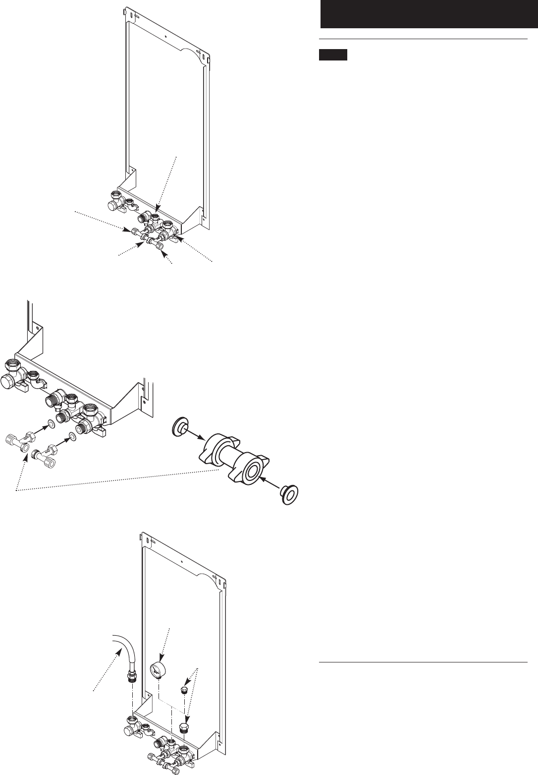
10.3 Fitting the Filling Loop
1. The filling loop supplied with the boiler can be
connected to the taps on the wall plate at this point.
2. The filling loop is to be connected between the mains
cold water inlet and central heating return isolation taps.
3. The loop and valves must be connected as shown in
the diagram (Fig. 44a).
4. Note the orientation of the flow direction arrows on
the stop valve and double check/stop valves.
5. Remove the end caps from the isolation taps and put
to one side. Connect the valves to the taps. Ensure that
the fibre washers supplied are used on these joints.
6. Connect the temporary loop, ensuring that the seals
are fitted.
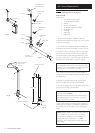
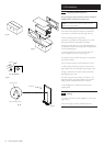
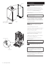
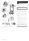
To fill, test and flush if required (Fig. 44c)
7. Take the blanking plugs from the kit, and using washers
supplied with the boiler, connect them to the central
heating flow and return taps, and the cold inlet tap. The
system can now be filled by opening the cold inlet supply
and stop valves.
8. If desired a suitable gauge can be connected to one of
the taps so that the system may be accurately
pressurised.
9. All joints, fittings and system components can now be
examined for soundness at operating pressure.
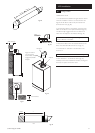
10. The system can be flushed by turning off the central
heating tap and connecting a suitable fitting to the loose
nut. From the fitting a hose pipe can be run to the
nearest convenient drain. When the tap is reopened the
system will flush.
11. Remove the blanking plug(s), pressure gauge and
flushing equipment from the appliance if used.
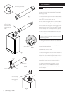
12. Continue with the installation and commissioning.
13. The filling loop must be disconnected and completely
removed after the system is pressurised.
14. Hand tighten the two previously removed end caps
to the stop valve and double check valve.
Fig. 44a
Fig. 44c
CH Return
Cold Inlet
Double Check Valve
& Stop Valve
Stop Valve
Temporary Filling
Loop
Fitting the Valves
to the Taps
Temporary Loop and
Flanged Washers
Blanking
Plugs
Pressure
Gauge
Hose and
Fitting
Fig. 44b