


38
© Baxi Heating UK Ltd 2008
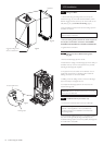
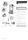
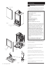
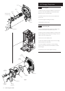
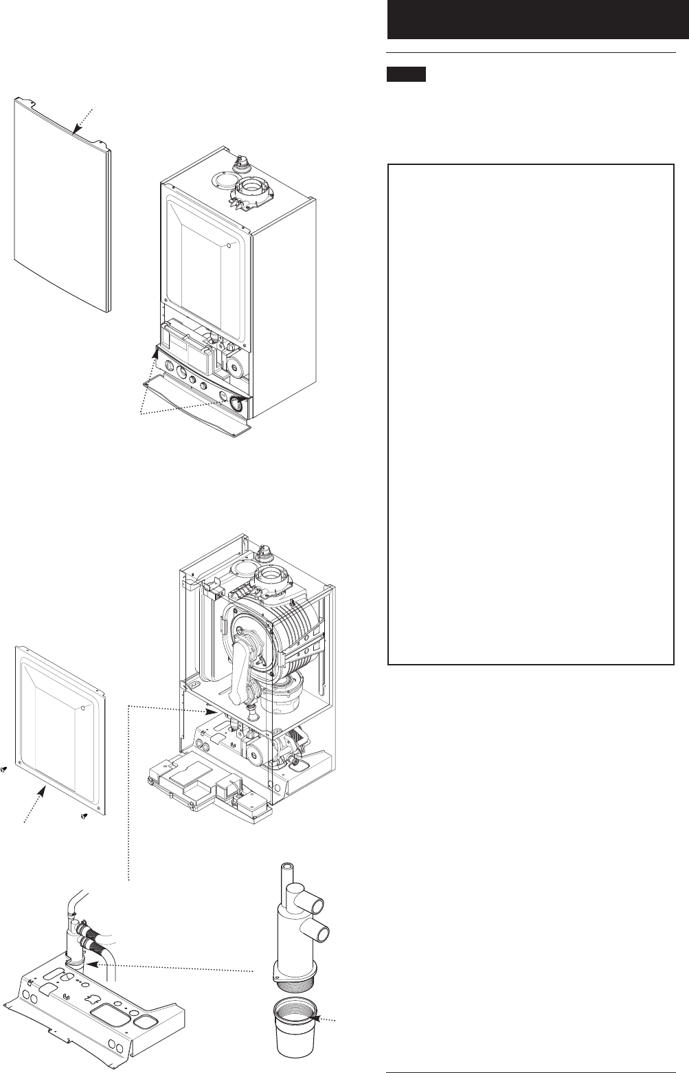
Case Front Panel
Fig. 73
Facia Panel Securing
Screws
Fig. 74
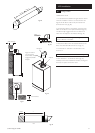
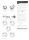
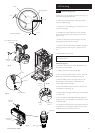
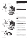
Inner Door
Panel
Fig. 75
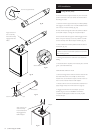
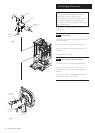
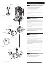
Sump
13.0 Servicing
13 .1 Annual Servicing
1. For reasons of safety and economy, it is recommended that
the boiler is serviced annually. Servicing must be performed by
a competent person in accordance with B.S. 7967-4:2007.
If a suitably calibrated combustion analyser is available it
may not be necessary to perform a full strip down of the
appliance. Proceed as follows.
Check for/inspect:-
Evidence of leakage of products of combustion
Water leaks
Heat stress
Deterioration such as corrosion
Visible condition of seals and joints
Flue system and ventilation
Condensate drain system
Operation at designed maximum heat input
If the above are satisfactory perform a combustion check
The CO/CO
2
ratio must be less than 0.004 and the CO
2
should be 8.7% ± 0.2 (max. rate) and 8.4% ± 0.2 (min.
rate). This can be adjusted - see Section 15.0 - if the
readings are incorrect. When correct combustion
readings cannot be achieved by adjustment a full strip
down must be performed - see below. Carefully check
items such as the burner, injector and heat exchanger
for blockage or damage, rectifying as necessary. Re-
check the combustion. Once satisfactory readings have
been achieved and any other defects corrected complete
the relevant Service Interval Record section of the
Benchmark Commissioning Checklist at the rear of this
publication.
Where no suitable analyser is available a strip down
service must be performed as described below.
2. After servicing, complete the relevant Service Interval
Record section of the Benchmark Commissioning Checklist at
the rear of this publication.
If a full strip-down is to be performed proceed as follows:-
3. Ensure that the boiler is cool.
4. Ensure that both the gas and electrical supplies to the
boiler are isolated.
5. Slacken the screws securing the facia panel. Lift the
outercase panel so that its securing tabs are clear of the facia.
Remove the panel, allowing the facia to hinge down (Fig. 73).
6. Remove the screws securing the inner door panel. Lift the
panel slightly to disengage it from the studs on top of the case
(Fig. 74).
7. Unscrew the sump from the bottom of the condensate trap
assembly (Fig. 75).
8. Remove any deposits from the sump and trap. Clean as
necessary and replace the sump.