


Part 7
OPERATION GUIDE
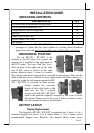
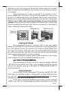
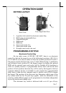
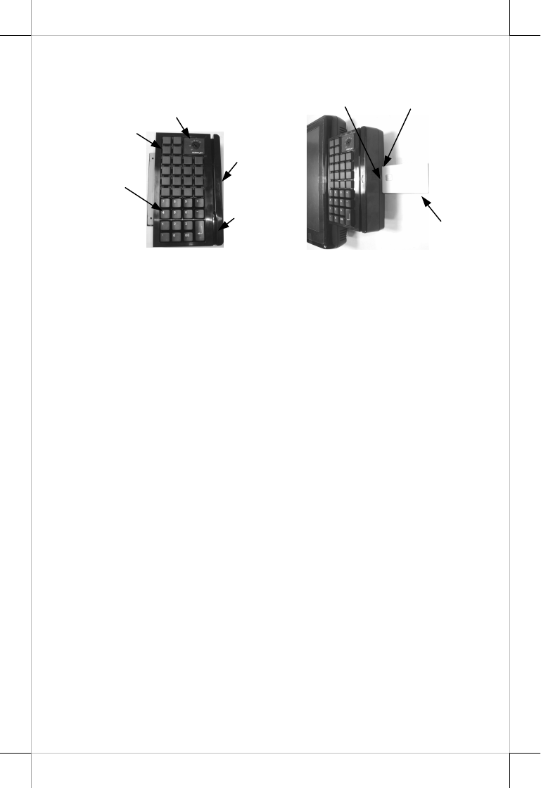
KEYPAD LAYOUT
1. 6 position lock switch for electronic control key
2. Multi-page programmable keys
3. Numerical keypad
4. MSR mark
5. MSR slot
6. Smart card reader slot
7. Smart card reader mark
8. Example smart card to be read
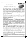
PROGRAMMABLE KEYPAD
Electronic Control Key
On top right corner of KP-300 / KP-300T, there is an electronic
control key that can be turned to one of the following 6 positions: LP, L0, L1,
L2, L3 and L4. It can only be taken out from the switch at positions L0 and L1.
The purpose of this electronic key serves 3 folds: When the key is switched to
(and extracted from) position L0, the keypad output (excluding the optional
MSR and the optional smart card reader) will be blocked off by hardware to
work as a security measure. A programmable answer back code for the final
position of the 6 position electronic key will be sent by the keypad to the host
computer whenever the key is switched to a new position for a programmable
delay time or when the host computer sends a specific code (E7h) to inquire
the keypad. The position of the electronic key determines which page of the
key content table for the 20 push keys applies, while the definitions of the
same key within different pages can be programmed so absolutely independent
to provide instant menu change over.
This electronic key switch is delivered with a set of 4 pcs of keys,
Fron
t View
Front Right Side View
6
8
7
1
2
3
4
5