


Part 3
INSTALLATION GUIDE
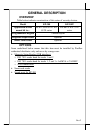
UNPACKING CONTENTS
Items packed in for Qt’y
The side mount programmable keypad itself 1
Posiflex product information CD 1
Transparent key caps for single key 20
Key clip 1
Control keys (4 pcs / set) 1
Legend sheets (4 sh. / set) 1
This manual 1
Note: Utility drivers for KP-300 / KP-300T can be found in the CD or DVD
packaged or please find for latest updates by visiting driver download
page of our web site:http://www.posiflex.com.tw/DriversDownload.asp
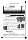
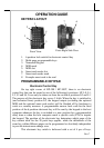
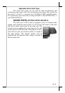
MECHANICAL FIXATION
For the KP-300 / KP-300T to be
installed in the KS series host system, the
upgrade kit is installed to the right edge of
the LCD panel. You may find two screw
holes on back of the right side of the main
unit of KS series as circled in the right
picture. Remove these 2 screws to remove
the cover for side mount upgrade kit as arrowed in same picture. Take out the
cable inside this cover as circled in lower right picture and then connect it to
connector inside the side mount upgrade kit KP-
300 / KP-300T as arrowed in same picture.
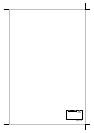
Gently arrange the excessive
length of this cable back in the
hole and use the 2 original
screws to fit KP-300 / KP-300T
back to the position originally occupied by the cover as in the
left picture. Please reserve the cover if there is chance to have
the side mount kit removed in the future.
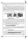
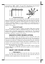
KEYTOP LAYOUT
Keytop Replacement
The keypad in KP-300 / KP-300T is organized into 2 parts: a 4 by 4
numerical keypad area and a 4 by 6 matrix minus a 2 by 2 square recess
programmable keypad area. However, this keypad allows some layout