P/N 472089 Rev. E 4-19-05
26
SET UP
The MiniMax NT LN Heater comes from the factory preset with a pool temperature setting of 78° F. and a
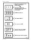
preset spa temperature of 100° F., and in the off mode setting. Once the power is turned on, the DDTC
board will do a self diagnostic internal check, during this time the display will first read “888”, then the
display will switch to three dashes “- - -“, this process takes approximately ten (10) seconds. The DDTC
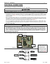
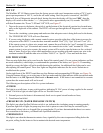
will then illuminate the “Power” LED and “Off” LED, see Figure 27.
1. Turn on the power to the heater; the switch is on the bottom of the electrical junction box located inter-
nally on the right side of the cabinet. The DDTC will now go through the self-diagnostic’s test as stated
above.
2. Turn on the circulating system pump and make sure that adequate water is being delivered to the heater,
The “PRESSURE SW” LED will now illuminate.
3. If you are using the heater with a remote control system, open the right door of the heater to access the
rear portion of the DDTC. Locate the three terminals marked “Pool” (J5), “Spa” (J6) and “Com” (J8).
If the remote system is a three-wire remote unit, connect the pool lead to the “pool” terminal J5, connect
the spa lead to the “spa” J6 terminal and connect the common wire to the “com” terminal J8. If the
remote system is a two-wire remote, the remote system will be used to turn the heater on for a selected
body of water, Pool or Spa, select which application you are working with and connect one wire to the
common terminal J8 and the other wire to either “Pool J5” or “Spa J6”. Close and latch the door.
LED INDICATORS
There are nine lights that can be seen from the front of the control panel, (five are system indicators and four
are mode indicators), which helps you understand the operation of the heater, see Figure 26. If something
should go wrong, the lights will aid in troubleshooting the problem. An additional four lights can be seen
after opening the control panel. These four lights are diagnostic indicators for the service technician to
troubleshoot the system.
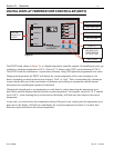
On the right front of the DDTC board there are four Buttons and corresponding LED lights, see Figure 26.
Using the buttons allows you to select one of the four modes and the lights indicate which operational mode
that the heater is in, Off, Spa mode, Pool mode or Remote mode. If the heater is not connected to a remote
system then the remote mode will not be used.
The following are descriptions of the five system indicators:
• POWER
The light is on at all times, in any switch position, indicating 24 VAC power is being supplied to the control
circuit. If it fails to light, no other light will be on. Possible causes are:
1. External power to the heater is disconnected; check service panel circuit breaker or fuses;
2. Transformer has failed.
• PRESSURE SW (WATER PRESSURE SWITCH)
This light is on when Spa/Pool Selector switch is on, indicates the circulating pump is running properly.
If pressure light fails to light, the pump may have lost its prime or water flow may be restricted by an
inadvertently closed valve or clogged filter or pump basket. If you have determined that there is no water
flow restriction to the heater, you should call a qualified technician.
• THERMOSTAT
This light is on when the thermostat contacts close, signaled by the water temperature falling below the
set-point, calling for the heater to fire to maintain the desired water temperature.
Section IV. Operation


