


10 C3427M-C (10/07)
SUSPENDED CEILING
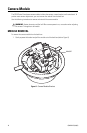
NOTE: You should install the camera module into the back box before installing the back box into the
surface. When installing the back box into the surface, rotate the camera module to access the mounting
holes (refer to Camera Module on page 12 for more information).
1. Pull video and power wires to the ceiling tile.
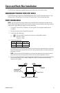
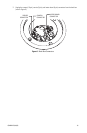
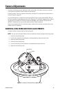
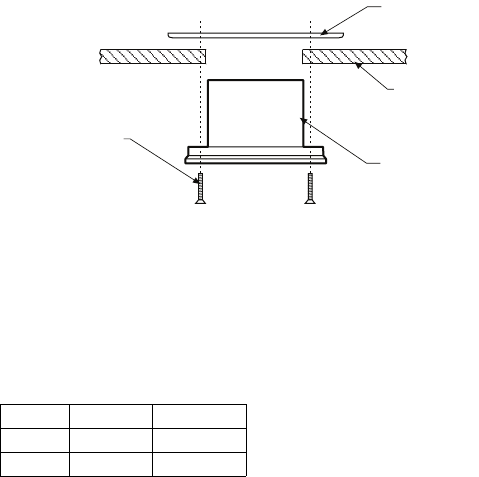
2. Mount the unit to the ceiling tile (refer to Figure 3):
a. Remove the ceiling tile from the ceiling.
b. Cut a hole 3.5 inches (9 cm) in diameter in the ceiling tile. Use the supplied adapter plate as a
template. Punch four screw holes in the ceiling tile.
c. Attach the back box to the ceiling tile and adapter plate with four supplied 8-32 x 1.25-inch
Phillips flat head screws.
d. Reinstall the ceiling tile with the unit.
Figure 3. Ceiling Tile Installation
3. Remove an adjacent ceiling tile.
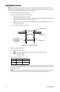
4. Connect the video cable/wires:
• BNC: Connect the BNC connector from the unit to a mating BNC connector.
• UTP: Blue wire = Video +
Gray wire = Video -
5. Connect the power wires.
AC operation only: If you are wiring more than one Camclosure to the same transformer, connect one
side of the transformer to the red wire on all units; connect the other side of the transformer to the
black wire on all units.
NOTE: Failure to connect all AC powered units the same way will cause the cameras to be out of
phase with each other and may produce a vertical roll when switching between cameras.
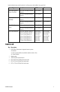
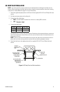
Voltage Red Wire Black Wire
12 VDC + Ground
24 VAC ~ ~
8-32 X 1.25-INCH
PHILLIPS FLAT
HEAD SCREWS
(SUPPLIED)
BACK BOX
CEILING TILE
ADAPTER PLATE