


C2941M-C (6/08) 11
Wiring Tables
CAT5 CABLE
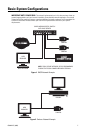
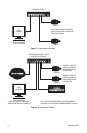
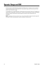
Connect a Cat5 cable to the RJ-45 network connector. The 8-pin connector includes video and PoE for the
camera. PoE (IEEE 802.3af) injects power over the same cabling that carries the network data, eliminating
the need for a separate power supply. This simplifies the installation and operation of the camera without
any degradation of network performance.
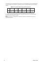
Refer to Table B for pin descriptions.
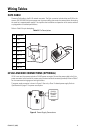
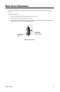
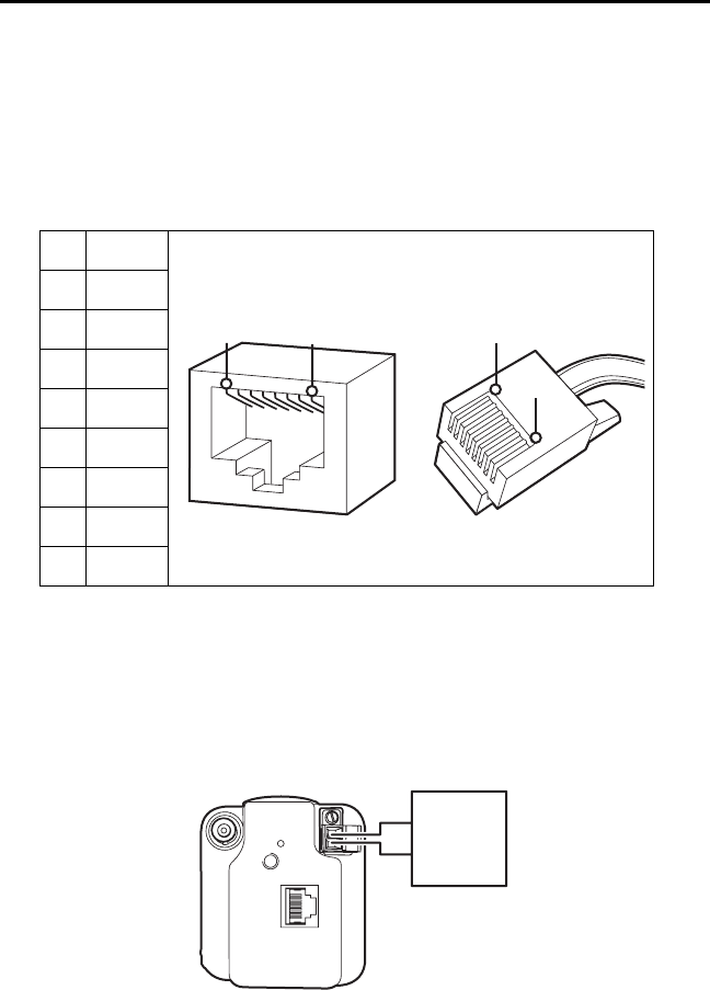
24 VAC AND BNC CONNECTIONS (OPTIONAL)
If PoE is not used, the camera includes a 24 VAC power connector. Connect the power cable to the 2-pin
power connector on the back of the camera using the terminal block connector (provided). Refer to Table C
for the recommend wire gauge and wiring distances.
The power supply connector is shown in Figure 6. Use only a Class 2 isolated power supply. Refer to
Specifications on page 21 for power consumption.
Figure 6. Power Supply Connections
Table B. Pin Descriptions
Pin Function
1TX+
2TX-
3RX+
4 PoE 1-2
5 PoE 1-2
6RX-
7 PoE 3-4
8 PoE 3-4
1
2
3
4
5
6
7
8
1
2
3
4
5
6
7
8
8
8
1
1
24 VAC
CLASS 2
ISOLATED
POWER
SUPPLY