


10 C2491M-C (1/06)
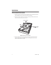
6. Install a 3/4-inch (1.91 cm) conduit connector in the conduit opening. Line up the
mounting holes in the base with the mounting holes of the mounting plate. Attach the
base to the mounting plate with the three 8-32 x 0.375-inch screws and lock washers
previously removed.
7. Attach the base to the conduit and then connect the power input wires to the power
wires of the ICS210 Camclosure. Refer to the following to connect the power wires:
24 VAC:
Connect power to the red and blue wires. The black wire is not used.
12 VDC:
a. Connect +12 VDC to the red wire and ground to the black wire. The blue wire is not
used.
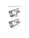
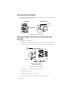
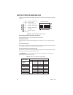
b. Reset the voltage jumper located on the camera power board inside the base of the
Camclosure. Refer to Figure 5. Remove the jumper from AC position and reinstall the
jumper on the DC position.
8. Connect the video cable. Make sure the boot covers the BNC connectors. Push the power
wires and video cable back through the conduit fitting.
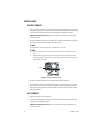
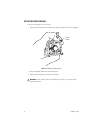
REINSTALL CAMERA MODULE
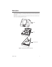
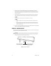
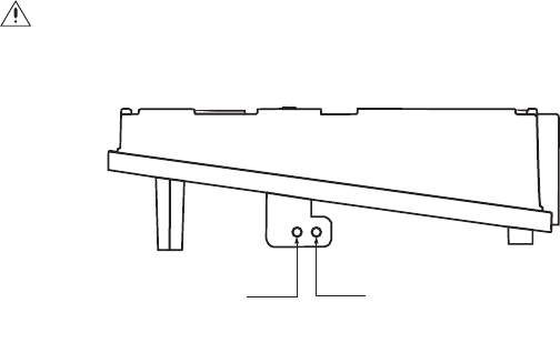
Reinstall the camera module. Refer to Figure 8. Make sure the top of the camera is oriented properly.
On the lens housing, look for the label that says TOP.
Figure 8.
Camera Installation
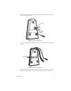
WARNING:
To prevent damage to the camera or lens, the camera must be installed in the
proper hole of the mounting bracket. If the camera is not installed in the correct hole, the
window of the enclosure may be forced against the lens.
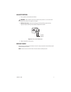
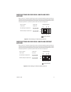
MOUNT CAMERAS WITH
6, 8, AND 12 MM AND
VARIFOCAL LENSES
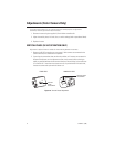
MOUNT CAMERAS WITH
2.9 AND 3.6 MM LENSES