


C1472M-E (1/07) 9
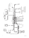
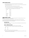
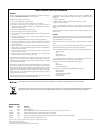
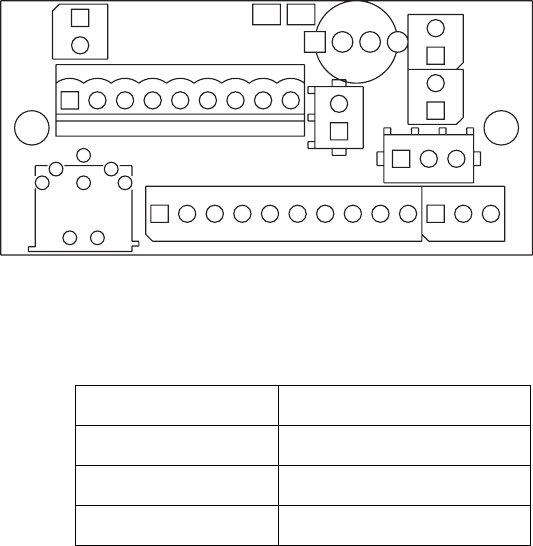
Figure 2. Circuit Board Component Locations
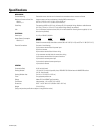
*Cable requirements:
75 ohms impedance
All-copper center conductor
All-copper braided shield with 95% braid coverage
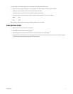
CAMERA MOUNTING
1. Attach the camera to the sled with the 1/4-20 Phillips screws that are provided in the parts bag. Attach the camera so that it is inside the
“U” shape of the sled.
2. Install the sled and camera in the enclosure:
a. If the camera’s lens is varifocal, extend the lens to its maximum length. This will ensure that the lens has enough clearance and will
not come in contact with the window during scene setup.
b. Place the sled over the mounting screws in the enclosure. Depending on the height required for the camera inside the enclosure, the
sled can be installed so that its base faces either the top or the bottom of the enclosure.
c. Slide the camera sled forward until the lens almost touches the window.
d. Tighten the two 10-32 Phillips screws and secure the camera sled to the rail.
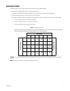
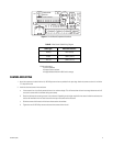
Table B. Video Coaxial Cable Wiring Diagram
Cable Type* Maximum Distance
RG59/U 750 ft (229 m)
RG6/U 1,000 ft (305 m)
RG11/U 1,500 ft (457 m)
GNDNTHI10987654321
AC IN
TB2
TB1
HIGH
INPUTS
LENS
LENS
COM
FOCUS
ZOOM
IRIS
PRST
COM
PRST
FOCUS
PRST
PRST
ZOOM
HI
CAM
CAM
5
CAM1
CAM2
DEF
P6
P2
P3
J1
P1
1
CAUTION!
VOLTAGE
PELCO
FAN
PA05-0003-
LENS CONTROL
HTRS
P5
TH1
P4
1