


10 C1472M-E (1/07)
WIRING CAMERA AND LENS
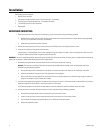
1. Bring a coaxial cable into the enclosure and connect the camera’s video output. Refer to Table B for cable distances.
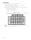
2. Bring wiring into the enclosure for camera synchronization and motorized lens if you are going to use these functions. Connect the wiring to
the circuit board. (Refer to Figures 1 and 2.)
HS4514 model only: Connect the wiring from the lens controller directly to the lens connection.
HS4514-1/-2 models with heater: Refer to Figures 1 and 2 and wire the motorized zoom lens control as follows:
a. Connect or wire the lens control from the camera to the LENS or LENS CONTROL connector on the circuit board.
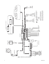
b. Wire the lens controller to the 10-connector INPUTS terminal on the circuit board as follows:
Lens Common Connector 1
Focus Connector 2
Zoom Connector 3
Iris Connector 4
Preset Common Connector 5
Preset Focus Connector 6
Preset Zoom Connector 7
Preset High Connector 8
WIRING CAMERA TO POWER
WARNING: Camera damage is possible if you connect your camera to the wrong connector. CAM 1 is enclosure power. Never plug your camera into
CAM 1 if the camera’s voltage is different from the enclosure’s voltage.
If your camera will use the same voltage as the enclosure, plug the camera into the CAM 1 socket on the circuit board inside the enclosure.
If your camera’s voltage will be different from the enclosure’s voltage, plug the camera into the CAM 2 socket only. Do not plug the camera into the
CAM 1 socket or you can damage your camera. CAM 1 has enclosure voltage on it.
HS4514 MODEL ONLY
Bring the camera wiring into the enclosure. If you are using 24 VAC refer to Table A, 24 VAC Wiring Distances, to determine the size of wire to
use. Connect the power leads to the camera.
HS4514-1/-2 MODELS WITH HEATER
If the camera will use the same voltage as the enclosure’s heater, there are two options for connecting power:
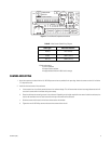
1. A three-pin plug with leads is supplied as loose equipment. Connect the leads from the plug to the camera as follows:
Brown AC HI
Blue AC NT
Green Ground
Refer to Figures 1 and 2 and connect the plug to the CAM 1 socket on the circuit board.
2. If both the camera and enclosure use 120 VAC and you ordered the optional 120 VAC electrical outlet accessory (O/I OUTLET), connect the
120 VAC plug to the camera and the three-pin plug to CAM 1.