


C1647M (3/05) 15
CONNECTIONS
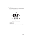
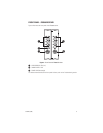
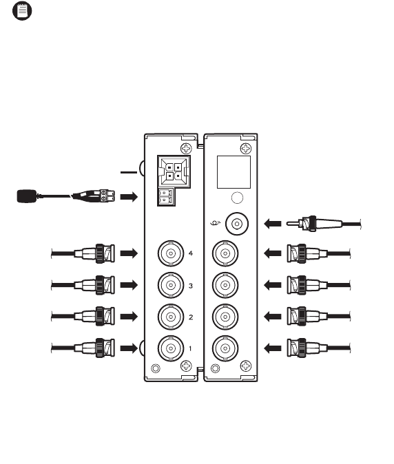
Connections to the FT8308 transmitter and the FR8308 receiver are made on the rear panel of
the modules and consist of the following:
• Power connection
NOTE:
A 12 VDC or 24 VAC power supply can be used to power the transmitter/
receiver when used as a standalone module. A 12 VDC power supply is provided. If a
24 VAC power supply is used, the power supply must be a Listed Direct Plug-In Power
Unit marked as Class 2 and rated as 24 VAC, 200 mA (minimum output).
• Fiber connection
•Video input connections (transmitter only)
•Video output connections (receiver only)
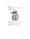
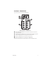
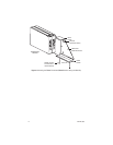
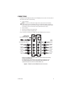
Figure 7 provides an illustration of FT8308 transmitter/FR8308 receiver connections.
Figure 7.
FT8308 Transmitter/FR8308 Receiver Connections
*REFER TO THE RK5000PS-3U/RK5000-3U FIBER RACK MOUNT CHASSIS INSTALLATION
MANUAL FOR INFORMATION.
THE STRIPED WIRE OF THE SUPPLIED 12 VDC POWER SUPPLY CONNECTS TO THE
PIN 1 SCREW TERMINAL (DC+) OF THE STANDALONE POWER CONNECTOR. THE
OTHER WIRE CONNECTS TO THE PIN 2 SCREW TERMINAL (DC-).
†
POWER CONNECTION
FOR STANDALONE MODULE†
FIBER
OPTIC
CABLE
POWER/ALARM
CONNECTION FOR
RACK-MOUNTED MODULE*
COAXIAL
CABLE
COAXIAL
CABLE
COAXIAL
CABLE
COAXIAL
CABLE
5
6
7
8
COAXIAL
CABLE
COAXIAL
CABLE
COAXIAL
CABLE
COAXIAL
CABLE