


C1647M (3/05) 11
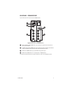
REAR PANEL - FR8308 RECEIVER
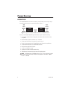
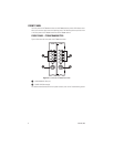
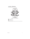
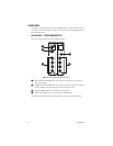
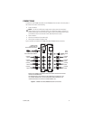
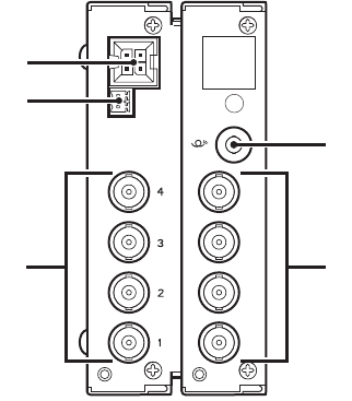
Figure 5 illustrates the rear panel of the FR8308 receiver.
Figure 5.
Rear Panel of FR8308 Receiver
ᕡ
RACK POWER/ALARM CONNECTOR, 4-pin connector for power/alarm connection of
rack-mounted module
ᕢ
STANDALONE POWER CONNECTOR, 2-pin connector for power connection of standalone
module; removable mating connector with screw terminals (not shown)
ᕣ
VIDEO OUT CONNECTORS (1-8), 75-ohm BNC analog video output
ᕤ
FIBER OPTIC CONNECTOR, ST or FC (dependent on FR8308 model)
For additional information about rear-panel connections, refer to the
Installation
section.
ᕣ
ᕤ
ᕡ
ᕢ
5
6
7
8
ᕣ